Alarm and monitoring systems. Seagoing ships
Alarm and monitoring systems are intended to monitor and register automatically all the essential parameters of the installation and display any abnormalities that have occurred. It saves time-consuming watchkeeping rounds, registers more information accurately, but is certainly no substitute for an engineer who, on his inspection round in the engine room, may find a small leak in a flange that can turn into a larger problem.
Seagoing ships
Alarm and monitoring systems are available in all sorts and sizes, starting from a small self-contained unit for 10 digital alarms with a common output for a group alarm and an audible alarm with accept and reset facilities.
Depending on the size and whether it is "manned" or "unmanned", larger systems are often composed of distributed input units linked together by a redundant network These can also send group alarms to the bridge instructing the bridge crew to reduce power or warning them of an automatic shutdown of the propulsion system. Usually, more complex systems have a graphic display with all kinds of software to analyze retrieved data. The engineer's logbook can be automatically generated, ready to be signed.
The engine room alarm and monitoring system includes the duty engineer's selection system with units in the engineers' cabins and the engineer's safety patrol system. This is a sort of egg-boiling clock, counting 27 minutes after the engineer enters the engine room or touches any button. It initiates an alarm in the engine room and engine control room, which must be cancelled by the engineer within 3 minutes. Otherwise, the system concludes that the engineer has a problem and initiates a general engineer's call.
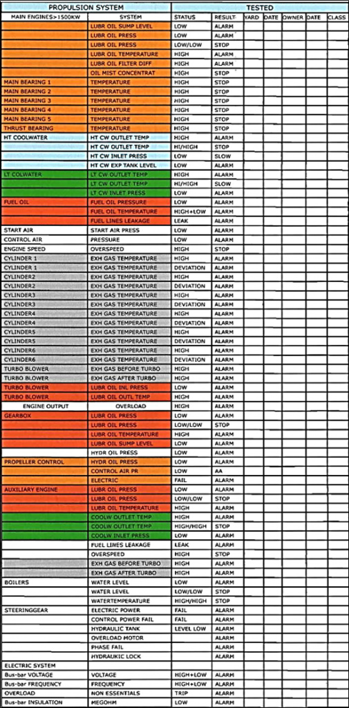
An example of minimum lists of alarms
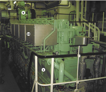
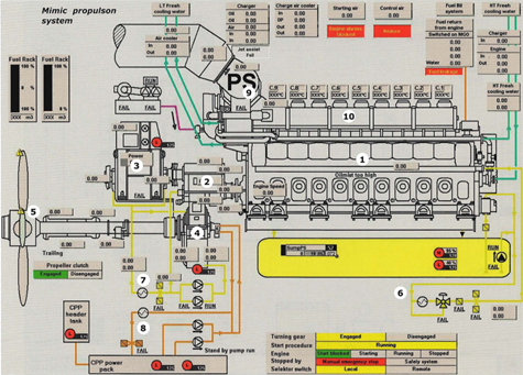
1. Main engine
2. Gearbox
3. PTO generator
4. Oil distribution box
5. Controllable pitch propeller
6. Main engine lubricating pumps
7. Gearbox lubricating pumps
8. Propeller hydraulic pump
9. Turbo blower
10. Casing over fuel system (fire prevention).
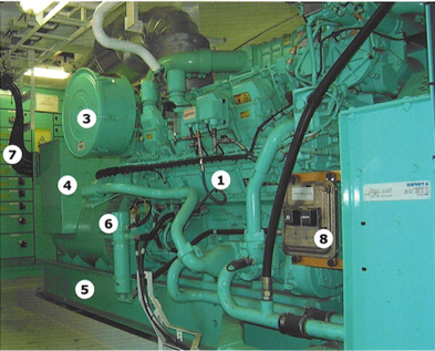
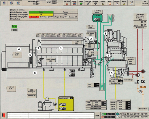
Auxiliary engine (generator set) and SCADA display of same engine
2. Governor
3. Turbo charger
4. Generator
5. Sump tank
6. Ventilator for generator cooling
7. Output power cables
8. Control pane
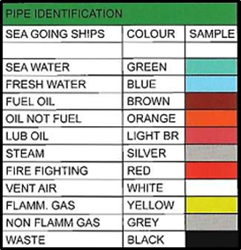
Colour Codes for piping systems
Piping systems in engine rooms are often colour coded to identify the contents of the pipes For easy reference, these codes are also used in some of the lists of alarms and measuring points
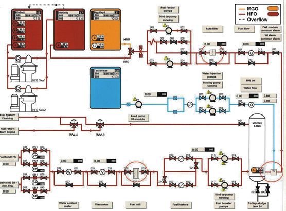
HFO - Heavy Fuel Oil, heavy fuel
 +7 (812) 4-673-673