 +7 (812) 4-673-673
ECDIS on board
SOLAS has set out a timetable for vessels engaged in international voyages to be fitted with ECDIS. After 1st july 2018, all High Speed Ship, passenger vessel > 500 GT, cargo ships and tankers > 3000 GT should be fitted with ECDIS. (Between 1/7 2012 and 1/7 2018 there are different dates for different types of ships) See IMO homepage.
Raster Chart Display Systems, RCDS
All the waters of the globe are not yet covered by official ENCs. When vector chart coverage is not available ECDIS may be loaded with official raster charts (RNCs). The system is then said to be working in RCDS-mode. In this situation official, fully corrected paper charts for these areas must also be carried on board. An RNC is defined by IHO (Special Publication No. 61) as:
Raster Nav igational Chart (RNC) means a digital facsimile of a paper nautical chart, produced by or distributed on the authority of a government authorized hydrographic office.
Integrated Navigational System
INS (Integrated Navigational System) is a concept used to describe a position source coupled in a network with several other instruments.
IMO has defined three categories of INS:
1. INS(A), which as a minimum provide the information of position, speed, heading and time, each clearly marked with an indication of integrity.
2. INS(B), which automatically, continually and graphically indicates the ship's position, speed and heading and, where available, depth in relation to the planned route as well as to known and detected hazards.
3. INS(C), which provides means to automatically control heading, track or speed and monitor the performance and status of these controls.
This enables the system to combine and display navigational information from several sensors, for collision avoidance (ARPA), reception of weather data, information for manoeuvres (conning display) and warnings for degraded information.
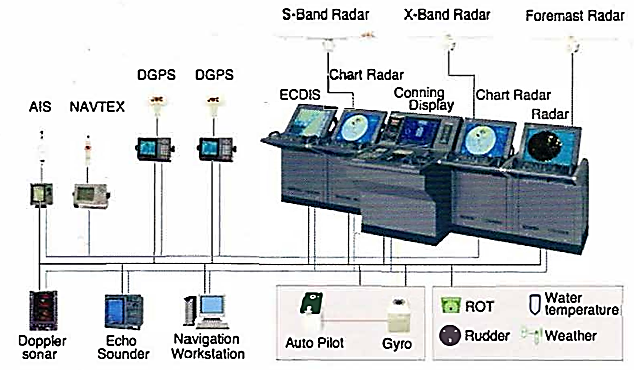
The ECDIS standard does not demand DGPS but the more accurate position information that this provides will result in more accurate course and speed information.Connection with the Internet enables access to weather information and chart correction information.
Radar and electronic charts can be overlaid (Chart radar). This gives a better overview in heavy traffic as well as the opportunity to control the position, speed and course of ones own ship. If position or course are incorrect then the electronic chart image and the radar image will not be perfectly overlaid.
A system may have both S-band and X-band radar connected, as they with their somewhat different characteristics are complementary.
With accurate position information, a correctly-scaled icon for the ship and exact electronic charts, the Navigator may have much use of the navigation system all the way in to the quay.
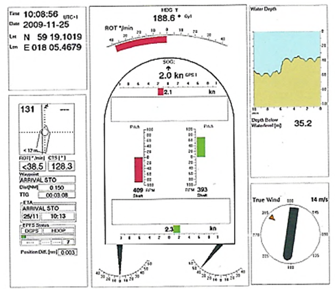
The Conning display gives a collected overview of the situation during harbour manoeuvres, including course, speed (also abeam speed for bow and stern), depth, rate of turn and so forth.
Bigger ships usually have one display that is dedicated for planning purposes. AIS can display its symbols on electronic charts, on the radar screen or both together. This improves the identification of radar targets.
There are many different models of autopilots with a more or less advanced functions. By coupling the autopilot to the navigation system the Navigator can set Track mode so that the vessel will be steered along the planned course line.
Navtex information can be displayed in a special window on the screen.
Conning Display presents the marry parameters of navigational information that the Navigator needs for assessing the situation during berthing
Integrated Bridge System
An Integrated Bridge System (I3S) can carry out navigation and also monitor other functions on board,
- communication
- loading, discharging and cargo control
- safety and security, watertight doors
- machinery control
- ballast
Performance standards for integrated bridge systems were adopted by IMO in 1996 (Resolution MSC.64(67))
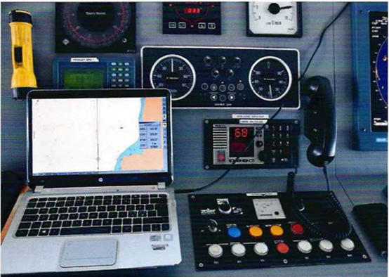
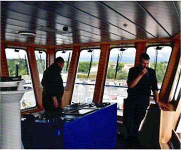
Instruments are continually being installed, exchanged and supplemented. An instrument may not always be mounted in the ergonomically most favourable position. As time goes by the instrument display may
become difficult to grasp quickly so it can require a thorough degree of familiarisation from the Navigator. The two circular instruments slightly above the centre of the picture are the Rate of Turn indicator and the Rudder Indicator.
The laptop belongs to the Pilot (Portable Pilot Unit; PFU) and is interfaced to the ship's navigational system via the Pilot plug.
E-navigation is a recent concept which is still under development. It includes more than just navigation by on-board systems. An IMO group has agreed on the following definition:
”E-navigation is the harmonised creation, collection, integration, exchange and presentation of maritime information onboard and ashore by electronic means to enhance berth to berth navigation and related services, for safety and security at sea and protection of the marine environment.”
Navigational systems can use analogue, digital and video signals.
The proper functioning of the network demands that the different parts can read each other's signals. The NMEA protocols have been designed by the National Marine Electronics Association.
The NMEA 0183 is an industry-standard eletronic signal specification that defines how data are to be transmitted from an electronic device. It ensures that data from different instruments will be compatible, even if the instruments have different manufacturers. However having several versions creates problems. Many instruments have sockets for both NMEA and manufacturer-specific protocols.
NMEA 0183 transmits information as "sentences". The information from the instruments is coded in a uniform way:
- All messages start with a dollar sign ($).
- The first two letters define the source of the signal, e.g. GP = GPS.
- The next three letters define the parameter, e.g. VTG = Velocity and Track Over Ground).
- The messages are split into data fields, such as compass course, separated by comma signs. The maximum length of a sentence is 80 symbols.
- A message is terminated by [CR] and [LF]. They are an instruction to begin a new message. The final information is a Check Sum to eliminate impossible readings.
- No more than two receivers ("listeners") may be allocated to one transmitter ("talker") and only one transmitter per receiver.