 +7 (812) 4-673-673
Sources of Error
If the timing of the radar pulse is not synchronised with the timing of the screen the image will be distorted. This can be checked by positioning the ship near a straight object such as a pier. If the echo of the pier is not a straight line then the set needs adjusting. Usually this can be done without the help of a trained engineer.
Directions and bearings will be shown incorrectly if the antenna or HEADING LINE is not properly oriented. Check this by steaming directly towards an object that gives a clean, narrow echo and compare this with the HEADING LINE. Adjust as necessary following instructions in the manual. A range error will be produced if the range rings are not correctly calibrated and a centering error will give rise to errors in both ranges and bearings.
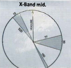
A blind sector will occur if the radar antenna is mounted so that the energy hits a mast or a chimney on the ship. A narrow mast may only weaken the pulse energy. Cranes on the foredeck may result in blind sectors if the antenna is mounted aft. Blind sectors can be detected by setting SEA CLUTTER to zero and increasing GAIN on a day when waves are of moderate height. Choose a scale so that wave echoes extend nearly to the edge of the screen. Sectors showing weak wave echoes denote sectors of reduced effect or blind sectors.
|
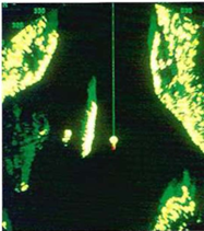
A blind sector revested in a rain shower |
Blind sectors should be displayed on a diagram near the radar. Picture below |
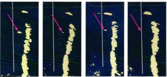
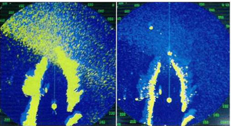
This image sequence shows a radar image with a HEADING LINE. To starboard of this in the upper part of the image, the echo from a ship. At the arrows is the echo of a buoy that varies in clarity
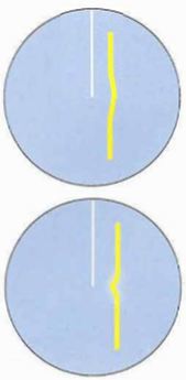
Радиолокационное изображение может показывать случайные ошибки, которые возникают из-за качества цели или настроек радара. Отражательная способность слабых или движущихся целей, таких как лонжерон в море, может варьироваться. В сочетании со слабой настройкой эхо может "мигать". Тот же эффект можно обнаружить, когда объект находится на пределе обнаруживаемости. Такие эхо-сигналы можно проверить, временно увеличив усиление.
 3.
Wrong settings give wrong image
3.
Wrong settings give wrong image
Incorrect settings give distortions of the radar image so that it does not correctly represent the information that the Navigator needs. Such a situation is the result of a combination of radar set characteristics
and the settings chosen by the Navigator. This is especially true in confined waters, when the -adar needs to be adjusted almost continually in order to register what the Navigator wants to see and to avoid registering what is not interesting.
Apart from the cases when targets don't give visible echoes because of incorrectly adjusted GAIN and TUNE settings, there are a number of other situations that produce distracting effects on the radar screen that the Navigator should try to combat. It should be Standard Operating Procedure to check all settings after taking over the watch. And it is also good practice to constantly "tweek controls, change ranges and adjust the GAIN/CLUTTER when searching for targets".
4. Sea clutter
The radar screen will almost always display some echoes that are produced by reflections from the lee side of nearby waves. The intensity of these echoes can be damped by the SEA CLUTTER control, which may be automatically or manually adjusted. The SEA CLUTTER control will also suppress other weak echoes so it isn't good practise to apply more damping than necessary and then operate continually at that setting.
Providing that it is not interfering with navigation it is common practise to allow some SEA CLUTTER to show on the screen, as a sign that the image is not being excessively damped. Do not apply automatic SEA CLUTTER damping without knowing how it affects the image!
The height of the columns show the extent of SEA CLUT TER damping
Gain
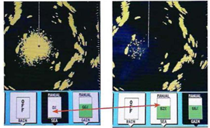
Offshore and at some distance from coastlines, it will not be necessary to make frequent adjustments to GAIN. In confined waters the GAIN must be adjusted frequently to visualise the information wanted by the Navigator. A buoy at long range may need a high GAIN to be visible, even though this will temporarily increase the sea clutter in the image. It may be necessary to study the image continuously for a time in order to detect the buoy amongst the clutter; the buoy image will be stable in one position while the clutter appears at random.
GAIN and SEA CLUTTER counteract each other so they frequently need to be tuned together in order to get the best image. Reduced GAIN will also give reduced sea clutter.
Radar has a function (TRAIL or TAIL) to increase the after-glow, which is the length of time during which echoes will be visible on the screen. This is particularly useful to help judge the risk of collision.
The tail on the echo of a spar close on the port side distinguishes it from SEA CLUTTER
The after-glow is also a help to discriminate between wave echoes and other echoes. Wave echoes don't recur at the same spot on the screen and therefore do not produce a trail.
Left: emerging from a channel the GAIN needs to be adjusted for more open water in order to get a good imageA higher setting reveals several targets on the other side of a lagoon
Rain echoes
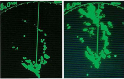
The effect of RA.INCLUTTER. Note the echo which was concealed in the rain shower (left-hand image) when RAINCLUTTER was not activated. The coastlines become narrower under the influence of RAINCLUTTER
5. False echoesSide lobe echo
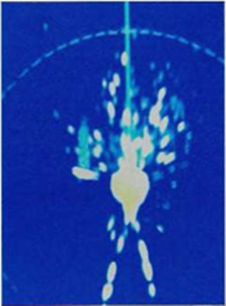
All radar antennae leak some energy outside the radar lobe: this energy is called side lobes. When passing a strong target at close range, so-called side-lobe echoes may appear on the screen. If necessary these can be decreased by decreasing GAIN. The topmost picture on the right shows side-lob echoes from a lighthouse and the picture below shows side-lobe echoes from a large vessel.
Indirect echoes
During both transmission and return radar pulses can be reflected by an object on board or by another target. The returning echo then appears to come from another direction. These indirect echoes look a little different from "true" echoes. Those that are caused by reflection from another target are shortlived, while those that originate by reflection from an object on board (see picture on the right) keep a constant position to the vessel and usually are easy to recognise as false echoes. If they are troublesome they can be damped using GAIN.
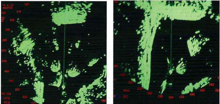
The left image shows a large number of echoes caused by reflection from a large vessel to port of the transmitting vessel. The right-hand picture shows the situation a few moments later
The left-hand picture shows the echo of a big ferry passing to port. Two so-called multiple echoes can be seen to the left of the ferry. The pulse has been reflected back and forth and has been registered each time.
The right-hand picture shows a false echo dead ahead at the same range as the big echo bearing 45° to starboard. The false echo is caused by reflection from the transmitting vessel's own mast. Some side lobe echoes are also visible
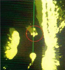
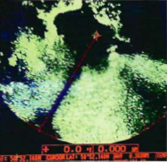
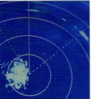
Power lines give a special echo. The cables themselves are too thin to make echoes, instead it is their magnetic fields that cause reflections. When approaching power lines in a narrow sound, it will appear as if a small ferry leaves the shore. No matter how the ship is manoeuvred the viTual ferry will always appear to be on a collision course. In the picture on the left the echo from the power lines is marked by a red circle.
Interference
Because different radar sets work on about the same frequency, interference can occur. The classical image of interference between another vessel's radar and one's own when sending on the same frequency is a pattern of slightly curved, dotted lines from the centre to the edge of the screen. The phenomenon is not very common, nor can it be mistaken for anything else, so it doesn't create any dif ficulty. Almost all radar sets are equipped with a function to decrease interference, INTERFERENCE REJECTION, IR. This function has less serious side-effects as compared to SEA CLUTTER and RAIN CLUTTER, so many officers leave it on all the time. This does, however, have a tendency to damp the background glow that is important for correctly setting GAIN.
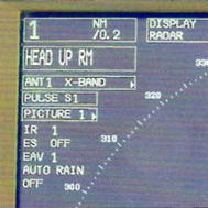
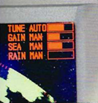
Information about the radar settings: scale is 1 mile, head up view, relative movement; 3 cm wavelength, short pulse, interference damping 1 (of 3), echo stretch off (echo amplification), echo average 1 (of 3), automatic rain clutter control off
Echo average
This function reinforces repeating echoes and helps distinguish targets from sea clutter. It suppress brilliance of unstable echoes and distinguishes small stationary targets such as buoys.
Echo stretch
Is a function that emphasizes radar echo to increase detectability of targets.