 +7 (812) 4-673-673
General ship layout and various systems
Bays / equipment
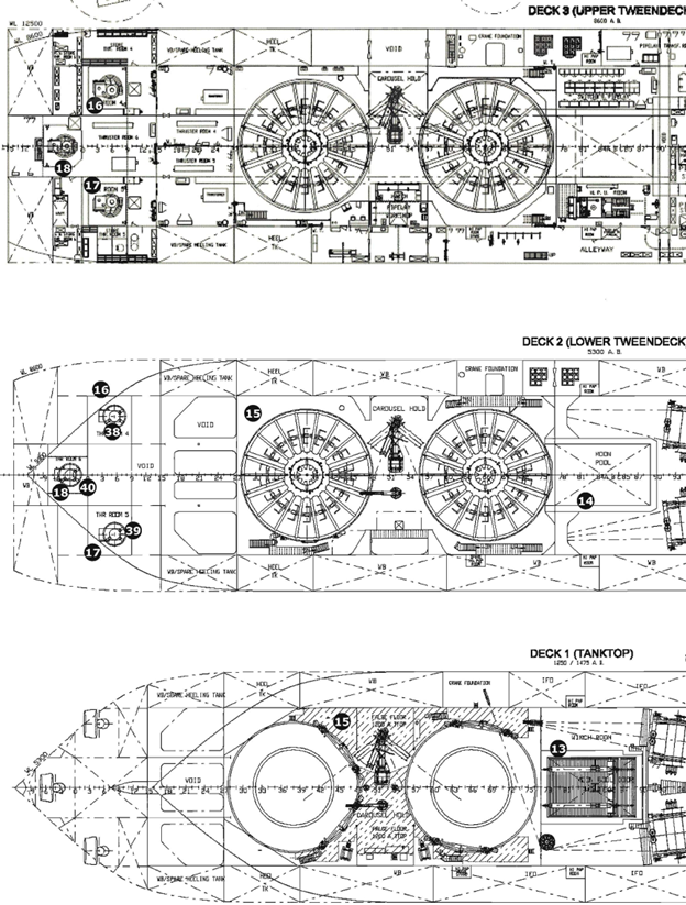
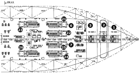
1. Retractable azimuth traster compartment 1
2. Tunnel traster compartment 2
3. Retractable azimuth traster compartment 3
4. Separator compartment 1
5. Separator compartment 2
6. Engine room port side 1
7. Engine room, starboard side 2
8. HV switchboard compartment 1 (port side)
9. HV switchboard compartment 2 (starboard side)
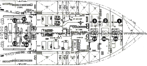
10. Engine Control Room (ECR)
11. LV switchboard compartment 1 (port side)
12. LV switchboard compartment 2 (starboard side)
13. Winch
14. Moonpool (shaft through the decks and bottom of the ship with the surface of the water)
15. Carousel drive
16. Azimuth traster compartment 4 (port side)
17. Azimuth traster compartment 5 (starboard)
18. Azimuth traster compartment 6 (center line)
19. Not used
20. Not used
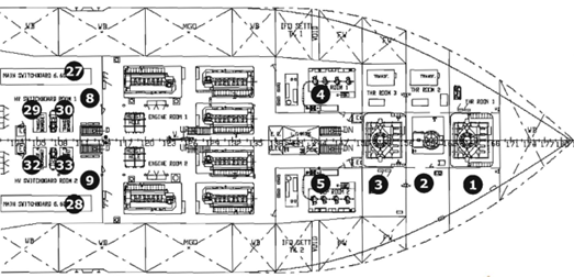
21. Diesel generator 1
22. Diesel generator 2
23. Diesel generator 3
24. Diesel generator 4
25. Diesel generator 5
26. Diesel generator 6
27. HV switchboard 1 (port side)
28. HV switchboard 2 (starboard)
29. HV / LV transformer 1 (port side)
30. HV / LV transformer 2 (port side)
31. LV switchboard 1 (port side)
32. HV / LV transformer 3 (starboard side)
33. HV / LV transformer 4 (starboard)
34. LV switchboard 2 (starboard side)
35. Azimuthal Thruster 1
36. Tunnel Thruster 2
37. Azimuthal Thruster 3
38. Azimuthal traster 4 (port side)
39. Azimuth thruster 5 (starboard)
40. Azimuthal traster 6 (center line)
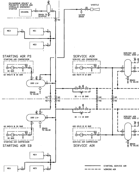
Start air compressors are located in each engine room and start automatically. Electric power for the compressors comes from different LV switchboards through different HV/LV transformers from two HV switchboards all located in the same engine room
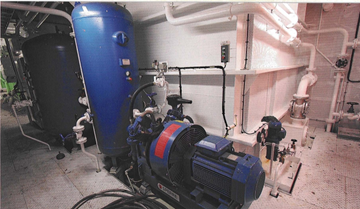
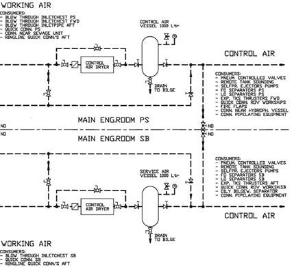
Working air compressor
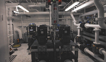
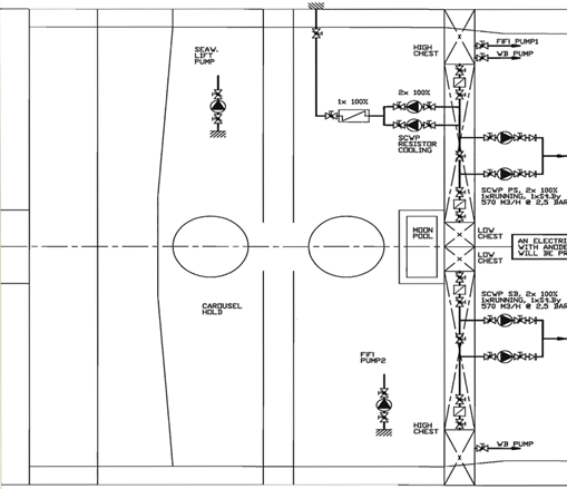
Two pumps for seawater cooling system
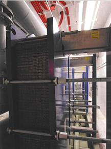
Two freshwater cooling coolers. Each cooler has the capacity of cooling three main engines
The seawater system consists of two pumps provided with an automatic standby starting system. Failure of a running pump will cause automatic starting of the standby pump. Each seawater system supplies cooling water to the individual heat exchangers of the main generator sets in that engine room as well as cooling water to the two heat exchangers serving the freshwater system.
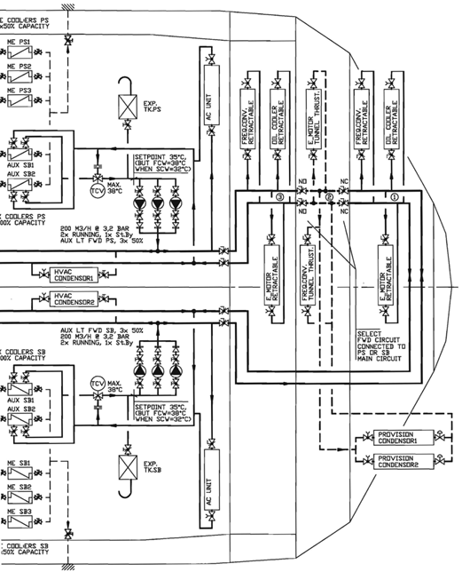
The freshwater service system is executed per engine room each with 3 50% pumps supplied from switchboards. The pumps are provided with an automatic standby starting system that starts the third pump when one of the two running pumps fails
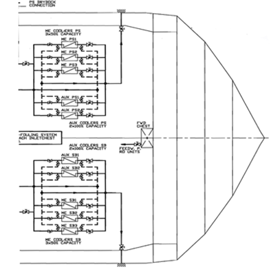
The freshwater service system is also used for the thruster cooling systems. The thruster cooling circuits are arranged in the same way as the electric power circuits for the thruster motors. Thus, thruster 4 which is powered by the SB switchboard has freshwater cooling from the SB engine room. Thruster 5 also from SB and thruster 6 from PS.
Consequently, a failure in an engine room freshwater cooling system can cause failure only of the cooling of the thrusters supplied from that engine room.
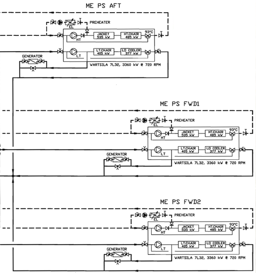
The main engine freshwater systems have engine- driven pumps. The system is duplicated per engine room.
One engine room is shown, the other engine room is identical
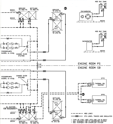
However, when the ship is operating on DP, the diesels are running on gasoil, and not on heavy fuel. The FMEA is drawn op for the DP mode. The fuel oil service units, with the heating system, are therefore not part of the FMEA. Fuel oil is supplied to the diesel engines out of tanks in the engine room, via fuel oil service units (heating, viscosity control) which have their electric supply from the low voltage switchboards
1 Retractable azimuth thruster room 1
2 Tunnel thruster room 2
3 Retractable azimuth thruster room 3
4 Not used
5 Not used
6 Engine room PS 1
7 Engine room SB 2
8 HV Switchboard room 1 (PS)
9 HV Switchboard room 2 (SB)
10 Not used
11 LV switchboard room 1 (PS)
12 LV Switchboard room 2 (SB)
13 Not used
14 Not used
15 Not used
16 Azimuth thruster room 4 (PS)
17 Azimuth thruster room 5 (SB)
18 Azimuth thruster room 6 (CL)
19 Not used
20 Not used
21 Diesel generator 1
22 Diesel generator 2
23 Diesel generator 3
24 Diesel generator 4
25 Diesel generator 5
26 Diesel generator 6
27 HV switchboard 1 (PS)
28 HV switchboard 2 (SB)
29 HV/LV transformer 1 (PS)
30 HV/LV transformer 2 (PS)
31 LV switchboard 1 (PS)
32 HV/LV transformer 3 (SB)
33 HV/LV transformer 4 (SB)
34 LV switchboard 2 (SB)
35 Azimuth thruster 1
36 Tunnel thruster 2
37..Azimuth thruster 3
38. Azimuth thruster 4 (PS)
39. Azimuth thruster 5 (SB)
40. Azimuth thruster 6 (CL)
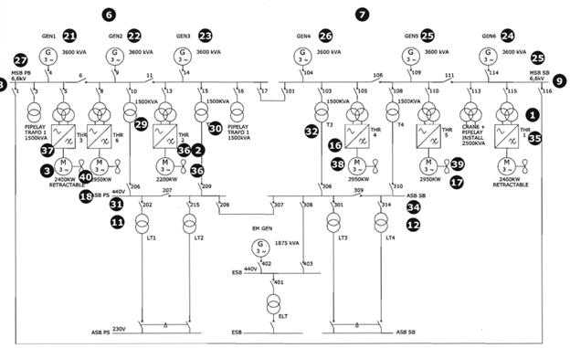
The one-line diagram above shows the main electrical power arrangement of the subject vessel.
The bus tie breakers in the main switchboards (8) and (9) can be open/closed to connect the generators two by two to different switchboards in three engine rooms. A single failure would then result in a 33 per cent loss of capacity and the vessel would be able to continue to operate
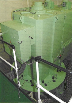
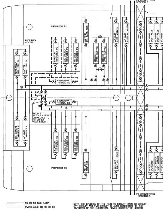
Frequency converter L-Drive aft thruster (motor with a vertical shaft located inside the vesse)
All supporting systems for the diesel engines and thrusters should be carefully assessed to ensure these are available with the primary supplies. The two 24 DC supplies have to be from different sources and a common failure must not cause failure of more than one engine.
Most HV switchgear requires an external power supply to close and open the circuit breakers. This is essentially different from LV switchgear where no-volt coils in the circuit breakers arrange for time delayed tripping at under-voltage. These circuits have to be included in the FMEA.
It is helpful to predetermine the location of the auxiliaries, the power for lubrication, pitch and direction hydraulics and all the control voltages. It is useless to design a completely redundant power supply system for thrusters operated by a single powered control circuit.
It is not allowed to get the main power from one engine room and the control power from the other, as failure of either engine room would stop operation. In this layout there are two engine rooms, with individual air, fuel, freshwater and seawater systems with fewer LV switchgear sections than in the HV systems.
The most disastrous result of a single failure is the failure of a complete HV switchboard and the associated LV switchboards resulting in a 50% reduction of propulsion capacity. When keeping the position of the vessel is essential, such as during operations in the vicinity of offshore platforms, the operator may not use more than 50% of the available power. If environmental conditions require more, the work must be stopped and the position abandoned.
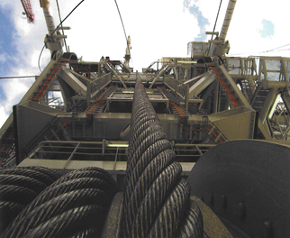
Abandon and recovery wire of the pipe laying installation