The magnetic compass
The earth resembles a large magnet whose magnetic field can be detected by magnetic compasses. Unfortunately the magnetic poles do not coincide with the geographical poles but are located some distance away. The magnitude of this error is sufficiently small so that over much of the earth's surface we can use the earth's magnetic field as a reference.
The magnetic field at the poles is directed at 90° to the surface of the earth while in an area between the poles (the magnetic equator) it has a horizontal orientation. The angle between the lines of force of the magnetic field and the horizontal plane is called the angle of inclination.
The magnetic compass is controlled by the horizontal component of the magnetic field. At the magnetic poles the magnetic compass is useless because the horizontal component is zero. The magnetic compass consists of one or more magnets hung under the compass rose, which is graduated in 360°. To increase its sensitivity the compass rose is mounted on a bearing, usually of sapphire, which is suspended on a needle. The compass bowl is filled with fluid in order to combine a high sensitivity with a smooth movement of the compass rose
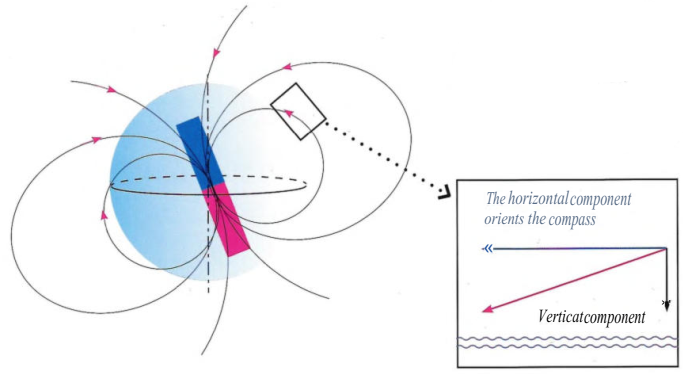
The earth's magnetic field appears as if it were created by a big magnet inside the globe, with a blue pole in the Northern hemisphere. The magnetic field is inclined at an angle to the axis of the earth
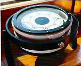
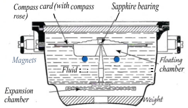
The sensors (magnets) of the magnetic compass are combined with the visualisation unit, the compass rose. The magnetic compass registers the magnetic field at the position of the compass. The compass is supported by gimbals, two concentric rings with supporting axes oriented at 90° to each other
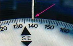 Lubber's line
The fluid damps the movements of the compass rose and also supports it with the help of a float. This decreases friction at the point so that larger, and therefor stronger magnets can be used. The expansion vessel is necessary in order to compensate for temperature fluctuations in the liquid. More compass fluid could be added through a hole with a plug, for example when an air bubble exist. The compass course is read off against the lubber's line, a vertical mark on the wall of the compass bowl and close to the edge of the compass rose. It is usual to mount the compass on the fore-and-aft-line of the vessel but if this isn't the case the line through the centre of the compass and the lubber 's line must be parallel to the vessel's fore-and-aft-line.
The illumination is usually red and should be equipped with a dimming device. If the illumination uses DC then the cables to the lamp should be plaited so as not to create an extraneous magnetic field.
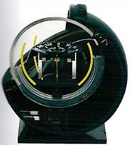 Spherical magnetic compasses have the same basic design and internal swivel mount. (Nexus)
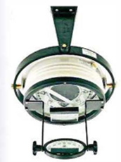
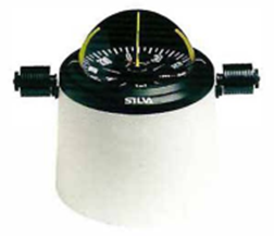
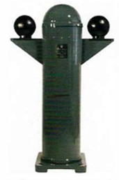
| Mounting the compass to the ceiling can sometimes help if the magnetic field is shielded.(Plath) | Spherical magnetic compass with internal gimbal bearing | A binnacle which contains the compass, illumination and magnets to compensate for the magnetic environment of the vessel |
Other magnetic field sensors
In addition to the compass needle/magnetic system to detect the magnetic field, there are three other types of sensor that are used in electronic compasses: the fluxgate sensor, the Hall-effect sensor and the magneto-resistive sensor.
The advantages of these sensors are that they can be sited in magneticallyinsensitive places on board while giving a signal that can be sent to slave instruments in other parts of the ship. The signal can also be used to steer an autopilot and in navigational systems.
The fluxgate sensor consists of a series of coils built up around a soft iron core: there are some differences between manufacturers. When the vessel is turning the fluxgate sensor has a lag time of 2 - 3 seconds, which is inconveniently long for fast vessels.
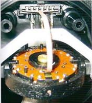 Gimbal Induction Compass
The Hall effect sensor is a thin layer of semi-conducting material (silicon) with the ability to produce an electrical signal when affected by a magnetic field. The strength of the signal is proportional to the strength of the magnetic field.
The Magneto-resistive sensor (MR), consists of thin layers of nickel-iron, whose electrical resistance varies as the magnetic environment changes. Compasses that use the Hall sensor or the MR sensor consist of three sensor elements mounted at 90° to each other (x,y,z). In order to give a correct course the compass should be mounted horizontally. If this is not possible then it is
possible to introduce a mathematical compensation factor. Several manufacturers avoid this necessity by adding built-in accelerators/accelerometers. These are also mounted in the x,y and z planes at right angles to each other. Electronic compasses exist that use magnetic field sensors, gimbal bearings, accelerometers and rate gyros in different combinations.
The compass course derived from electronic compasses can be displayed on a variety of instruments, corrected electronically for sources of error and be linked in networks
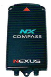
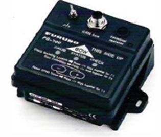 Some magnetic field sensors
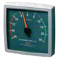
|
The course indicator displays any deviation from the set course (iockedon course) |
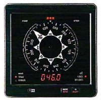
An instrument with both a compass rose and digital display |
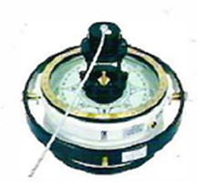
Placed on the compass this sensor transmits signals to the autopilot |
 +7 (812) 4-673-673