 +7 (812) 4-673-673
Compasses
The compass is used to determine directions on the surface of the earth, i.e. courses and bearings. Three types of compass are in use on board:
- Gyrocompass
- Satellite compass
- Magnetic compasses
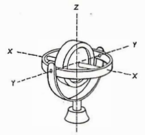
The heart of the gyrocompass is a rapidly rotating wheel, a gyroscope. The characteristics of the gyroscope lie at the heart of the gyrocompass. The first characteristic is that a freely-suspended gyroscope will maintain its rotational direction in space. When a gyroscope is placed on a flat surface such as a table, an observer will experience that the axle of rotation is changing by 15° per hour in relation to the room. However in relation to space it has maintained its orientation while the earth itself has rotated by 15° (=360/24).
There are many everyday examples of the gyro effect, which causes a rotating wheel to resist a change in direction. For example when rotating a disc grinder will tend to resist an attempt to change its orientation.
The second characteristic is that when the rotating gyro axis is subject to a force then the gyro will not change direction in line with that force, but at 90° to the rotation axle. So when a gyro with a horizontal axis is subjected to a vertically-acting force then the rotation axis will change direction in the horizontal plane. This effect is called precession.
The gyro is made north-seeking by using the earth's gravitational force. The principle is to hang a weight under the horizontal axis of the gyro.
 Maps from mapAbiiiiy.com
 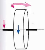 Precession causes the gyroscope to rotate in a direction oriented 90° from the direction of force
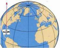
As the earth rotates the gyro seeks to maintain its direction in space, so the horizontal axis tends to become elevated. The tendency of the weight to keep its orientation towards the centre of the earth applies a force to the rotational axis. The downward force on the elevated end of the gyroscope causes the gyroscope to precess, with the result that the orientation of the gyroscope follows the meridian. In other words the gyroscope has become North-seeking.
This North-seeking process is rather slow. The gyroscope doesn't immediately align with the meridian but swings from side to side of the meridian if the gyro isn't damped. Even a damped gyrocompass can swing for several hours after starting up.
A number of manufacturers have developed the gyrocompass since its introduction at the beginning of the 20th century with the result that many technical refinements have been introduced. So it is essential to consult the instruction manual to find out the operating specifics of each compass.
There are several technical solutions for the "bob" or "pendulum" necessary to make the gyro North-seeking, depending upon the manufacturer. One way is to have connected vessels filled with oil or mercury. Another solution is to suspend a ball in a fluid within a container with a weighted bottom. The ball floats in a fluid in an outer container.
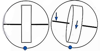
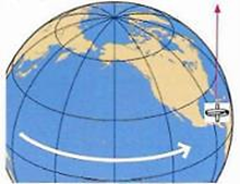
The principle of the search for the North. The weight creates a precessional force to counteract the gyroscope's tendency to raise the axis of rotation as the Earth rotates. This precession returns the gyroscope to its orientation along the meridian
The gyro setting in modern compasses is controlled electronically. Once again different manufacturers have different technical solutions.
The principle for electronic control is to register the gyroscope movements by sensors. These produce electrical signals that are proportional to the direction and size of the movement. After amplification the signals activate electromagnets and electric motors which cause the gyroscope to precess. Digitally controlled gyrocompasses have a shorter adjustment time compared to mechanical ones.
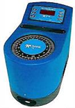 A small gyrocompass, consisting of gyro housing, settings and compass rose. (Brown. Teh edyn)
A gyrocompass with a compass rose intended for mounting at the helm. Further slave compasses can be installed as required. (Images: Raytheon Anschutz GmbH, Germany)
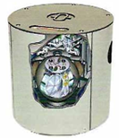 Image: Raytheon Anschutz GmbH, Germany
The gyrocompass consists of:
- The sensor part - the gyroscope itself
- The electrical supply
- The control system which transmits signals to the compass rose, slave compasses, radar, etc. It is normal to install the master compass in a separate room while the repeater compasses can be found at the helm and on the bridge wings.
- A system to compensate for sources of error. If this is not installed then errors have to be corrected by calculations.
1.1. The gyrocompass: sources of error
Orientation error: caused by a failure to align the lubber 's line with the fore-and-aft-line of the vessel. In some compasses this can be compensated electronically
Transmission errors: these occur during transmission from the mother compass to the slaves. It is standard operating procedure to routinely check that all the compasses show the same course.
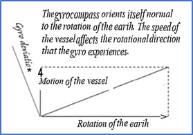
1.2. Speed error (gyro deviation)
As the vessel gets under way an error is generated that is a function of latitude , speed and course. This can be adjusted automatically if the compass is supplied with information from other instruments. If this is not possible then manual adjustment must be made, either by installing a corrector or with the help of a correction table.The North-seeking tendency of the compass is weaker at high latitudes.
1.3. Quadrantal error
Rolling creates a force that affects the forces generated by the gyrocompass weights. There is no effect on a North/ South course as the force of the pendulum mechanism acts along the course, which is along the meridian, generating no error. Although the gravitational sensor is affected on a West/East course, the effects cancel out to give no average error. Errors only arise on intercardinal courses (NE, SE, SW, NW).
Mounting the gyro unit deep in the ship and close to the centre of roll decreases these errors.
1.4.Ballistic error
A sudden change of speed or course will cause the gyro axis to deviate from its equilibrium position. This gives a so-called ballistic effect.
Compasses having two gyroscopes oriented at right angles have a lower sensitivity for large changes of speed and course.
There are also gyrocompasses that are coupled to an electronic magnetic compass (Transmitting Magnetic Compass). This supports the system with a course signal if the gyrocompass should experience a breakdown and acts as a off-course alarm.
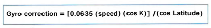
1.5. Corrections
Most gyrocompasses have an arrangement for the direct compensation of the course in the compass. This may be performed manually or automatically using signals from the GNSS.
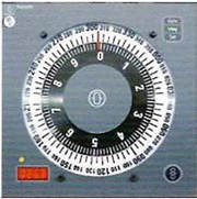
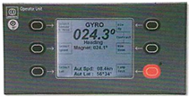 Panel to Anschutz gyrocompass with possibility for manual input of speed and latitud
It is also possible to make corrections from tables, or calculate the error according to the following formula:
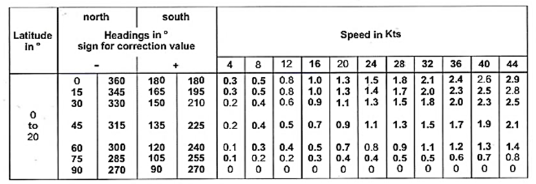
Gyro deviation table. In order to calculate the gyro course for a planned route, change the sign of the correction factor.
IMO Gyro compass performance under operational conditions
-
When switched on in accordance with the manufacturer’s instructions, the compass should settle within six hours in latitudes of up to 60° when rolling and pitching with simple harmonic motion of any period between sin and fifteen seconds, a maximum angle of 5°, and a maximum horizontal acceleration of 0.22 m/s2
-
The repeatability of the settle points error of the master compass shall be within ± l° x secant latitude under the general conditions mentioned in paragraphs 6.1 and 8 and including variations in magnetic field likely to be experienced in the ship in which it is installed.
In latitudes of up to 60° :
- .1 the residual steady state error, after correction for speed and course influences at a speed of twenty knots, shall not exceed ± 0.25 x secant latitude;
- .2 the error due to a rapid alteration of speed of twenty knots should not exceed ± 2°;
- .3 the error due to a rapid alteration of course of 180° at a speed of twenty knots should not exceed ± 3° ;
- .4 the transient and steady state errors due to the ship rolling, pitching and yawing, with simple harmonic motion of any period between six and fifteen seconds, maximum angle of 20°, 10° and 5° respectively, and maximum horizontal acceleration tool exceeding lm/s2, should not exceed 1° x secant latitude.
The maximum divergence in reading between the master compass and repeaters under all operational conditions should not exceed ± 0.5°.