Electric motors
Electric motors convert electrical energy into mechanical (rotating) energy and with that have the reverse function of generators.
The major categories are related to an AC or DC power supply but then the choice is endless from the very small step-motors used in robotic applications to very large motors in the MW range.
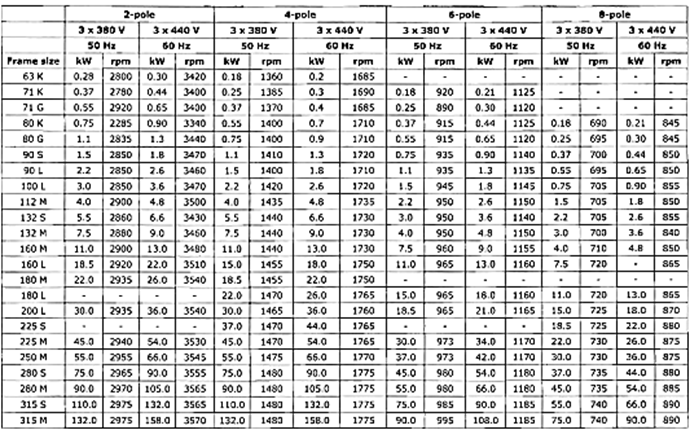
Electric motors come in all shapes and sizes and suitable for a wide range of power supplies. As with generators the applied frequency and the number of poles in the stator determine the speed of the motor. Nowadays the most widely used electric motors are the 3-phase alternating current asynchronous motors with a squirrel cage rotor. An overview of this type of motor, in the range from approximately 0.3kW to 160kW, for various voltages, frequencies and speeds is shown on the next page.
This chapter will concentrate on this type of АС-motors. When using variable speed drives AC-mo- tors can be precisely controlled for starting, speed and torque.
Electric motors are available in different housings for foundation or flange fitting. They are also available with different protection classes against the ingress of solid particles and water (IP-class) and for use in an explosive environment (Ex-class).
Ex-motors are available with the following classes :
- flameproof Ex-d
- pressurized Ex-p.
When additional cooling capacity is required an extra cooling fan can be installed on the main electric motor. When such a motor is also totally enclosed these motors are also referred to as TEFC for Totally Enclosed, FanCooled [motors].
Testing AC-motors
All AC-motors have to be tested and when the power rating is above lOOkW they have to be certified by the classification society.
The basic AC-motor test consists of:
- High voltage test
- Meggertest again
- start current
- no-load current
- full-load current
- consumed power
- supplied power
- efficiency
- power factor
- start torque
- nominal torque
- speed range
- housing temperature
- winding resistance cold
- winding resistance hot after the full-load test
- heat run to determine the maximum winding temperature under continuous load.
The maximum permissible winding temperature depends on the type of winding insulation used, the temperature of the cooling air or the temperature of the cooling water. As an example the table on page 105 gives an overview of limits to temperature rise for aircooled rotating machines. The maximum temperature rise is determined in a heat run. The heat run is a test where the motor is loaded with nominal load until the temperature of the housing stabilizes. Before the start of the test, the temperature of the motor and resistance of the windings at this temperature is measured.When the housing temperature stabilizes the resistance of the winding is measured again. From the two values obtained, the temperature rise can be calculated
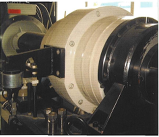
under test and the water brake (dynamo metre)
A motor test stand at a motor manufacturer showing the motor
The equipment necessary for a heat run is called a dynamometer, a brake which converts power produced by the electric motor into heat. This brake is also free moving so that torque can also be measured.
TIME
AIR IN 0 C AIR OUT ° C DIFF " С 8:00 18 18 0 8:30 18 20 2 9:00 19 22 3 9:30 20 25 5 10:00 21 30 9 10:30 21 36 15 11:00 22 43 21 11:30 23 44 21
For large motors the heat run, with a mechanical load, can be replaced by using two frequency converters to supply the motor. One frequency converter supplies the motor with the rated voltage and frequency and the other with a lower than nominal voltage and frequency. With the motor running at no-load speed on the first frequency converter the variable voltage is increased so that the total current of the two power sources is equal to the rated current of the motor. The advantage is that the power consumed comes from the losses that produce the heat. The rest of this test is the same as for the heat run as described above.
Code of standardized frames for the various types of standardized electric motors

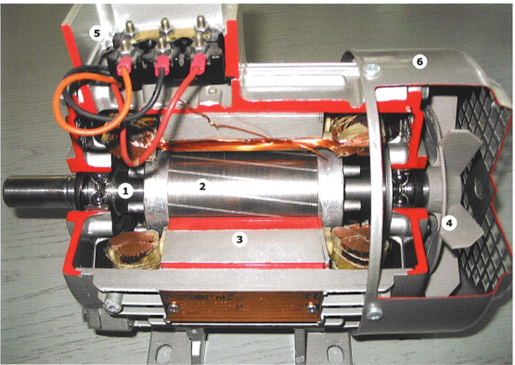
Squirrel cage motor
2. Squirrel cage rotor
3. Stator Windings
4. Cooling fan
5. Connection box
6. Protection cover
 +7 (812) 4-673-673
