Dynamic positioning
This paragraph refers to special ships which are required to stay in position during operation, without the use of anchors or other means fixing them to the seabed.
Dynamically positioned ships include crane vessels, ships for cable laying, pipe laying, pipe trenching, stone dumping, diving support, dredgers and even bunker boats, large yachts and recently, passenger ships visiting exotic locations.
The same systems, known as autosail and auto track, are also used to control a ship when moving from one position to another and when the environment cannot be disturbed by anchors. More and more ships are equipped with such control systems.

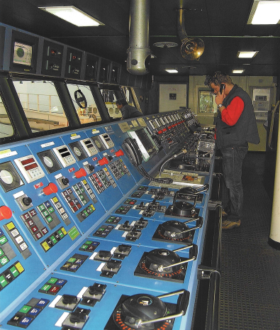
The figure shows the individual thruster control console of a crane and pipe laying barge. These controls are not for operation, as this is nearly impossible for an operator, but for testing procedures of individual thrusters. In the center of the console is a combined control unit, enabling the combined handling of all thrusters to obtain a total output in force and direction.
The basic design criteria, what, where and how are very important for DP applications.
1. DP Notations
Class 1 is for simple work with a single automatic control system having a manual back-up, where a loss of position would not lead to a critical situation.
This can be an offshore standby vessel, a yacht or perhaps a passenger ship staying in position with a manned bridge.
Class 2 is for more complicated work with a duplicated automatic control system, where loss of position could lead to more critical situations. Examples are ships for cable laying, pipe laying, trenching, or stone dumping.
An FMEA is required for the control system and the propulsion controlled by the system.
A single failure , such as fire and/or flooding of a space, has to be considered. Notation (AA).
Class 3 is the highest class in redundancy and in use for high- tech deep water pipe laying ships, heavy-lift ships or diving support ships, where loss of control could lead to dangerous situations.
An FMEA is required,for the control system and propulsion system, based on a single failure. Flooding and/or fire in a space is also considered. Notation (AAA) or DP3.
When flooding and fire are a consideration for the FMEA, the cable routing from the duplicated control systems to the thrusters and other controlled equipment is vital.
2. DP systems lay-out
A dynamic positioning sytem is built up from hardware, such as propellers and thrusters, where output and direction is controlled by computers, which get information (software) from various sensors regarding wind, position, heading, speed etc.
Depending on the classification of the DP system, redundancy is provided by the number and power of thrusters, computers and inputsensors. The computers process the input and translate this into commands to the thrusters.
The result for the ship may be to stay in position or move according to a defined course and over a defined distance.
It can also be used to sail along a defined track with waypoints, mostly used for cable laying operations which can be done at speeds up to ten knots.
An essential part of a DP system is the Power Management System (PMS). This system regulates the generation and distribution of electrical power. Special operational load calculations are made during the design period including load flows, selectivity issues and switchboard configurations like open or closed bus tie breakers.
DP system designers will use resulting data to calculate the DP capacity of a ship and produce a so- called DP-footprint. A DP-footprint indicates the operational limits of a DP-ship in relation to the environmental conditions like current and wind and the available thrust.
Redundancy is often determined by a Failure Mode and Effect Analysis (FMEA), a requirement for all ships with a high DP notation.
This analysis does not address the control system only, but all equipment, electric or not, required to stay in position or to perform auto-sail or auto-track as defined in the first design criterion "WHAT".
3. Input sensors
These environmental sensors consist of:
3.1 Gyrocompass
Two or more gyrocompasses determining the heading of the vessel.
3.2. Vertical reference units
Two or more vertical reference units which determine roll and pitch of the vessel
3.3 Wind speed and direction
Two or more wind speed and direction monitoring systems enabling the system to react to wind force and gusts before the vessel starts moving.
3.4 DGPS systems
Two or more DGPS systems determining the position of the vessel. Also heading and speed are calculated, provided the ship is moving. Two or more differential receivers for the correction signals of the global positioning system.
3.5 Taut wires
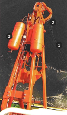
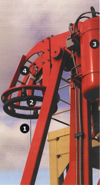
A taut-wire system is basically a self-tensioning winch keeping a steel wire, connected to a weight on the seabed, under constant tension. The wire is led through a gimbal head with transmitters collecting data about the directional angle of the wire in two directions and thus determining the relative movements of the ship.
Computers calculate the movement from the angle, corrected by the angle of the ship from the vertical reference units and the measured wire length or water depth.


2. Ring is limit switch for upper position of taut-wire weight
3. Heave compensator
4. Angle sensor for transverse movement of vessel.
3.6. Radar based position systems
Other position reference systems are ARTEMIS: A radar-based system measuring distance and heading from one or more transmitters located at a fixed location.
3.7. Laser based systems
A more modern above water system is FANBEAM, a laser-based system which measures distance and heading from a reflector at a fixed location. Sometimes this system reacts to the reflectors on safety clothing.
3.8. Under water position systems
Under water, there are SONARbased systems reacting to transponders positioned on the seabed. A transponder replies to the sound signals transmitted from the ship and again, distance and heading is measured.
4. Sensor off-sets
For an accurate system all the relative distances between the DGPS aerials, the locations of the taut wires, the LASER directors and the SONAR beams, have to be known and fed into the computer systems. The signal input to the computer has to be corrected for all these permanent off-sets. Also the changes as a result of the movement of the vessel are corrected by the computer system.
As an example the system will try to keep the antenna of the DGPS system in a fixed position. Rolling of the ship will move the position of the antenna and if not corrected will activate thrusters. The same will happen if the operator changes from DGPS1 to DGPS2 if the system does not know the off-sets of the antennas.
The location on the ship to be kept in place by the DP system can be selected depending on the type of work. Depending on the type of work, and the location of the tool on board to do the work with, offset can also be determined for the tool. For a stone dumper, the end of the fallpipe can be the important location. For a crane vessel the position of the hook

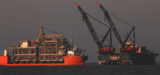
DP Cranevessel is making preparations to lift a topsides from the submersible heavy cargo ship
5. Locations and types of propulsors
These different applications determine the required locations and types of propulsors. The name propulsors is chosen to address the variety of thrusters such as:
- Variable pitch fixed speed unidirectional thruster
- Fixed pitch variable speed omni-directional thrusters
Both types are also available as Azimuth thrusters where the direction of the thrust can also be controlled, azimuth thrusters are made as fixed and as retractable. Fixed pitch variable speed reversible tunnel thrusters as well as variable pitch fixed speed tunnel thrusters are used. These thrusters can be diesel driven or diesel electric from one or more generators.
 +7 (812) 4-673-673