 +7 (812) 4-673-673
Connecting AIS TRANSAS T105 to a computer
There are 2 options:
OPTION 1
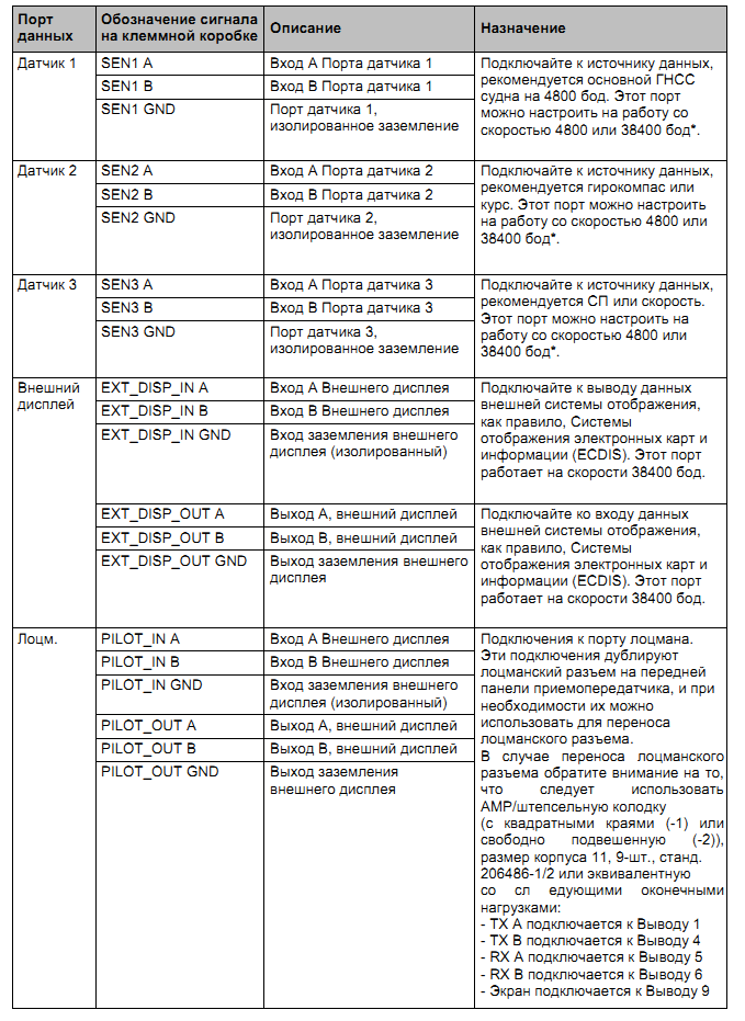
In the AIS 105 class A terminal box there are ports for connecting external sensor inputs and output to external devices. Accordingly, there are inputs, there are outputs. At the request of the registers, a gyrocompass is connected to the AIS (it is possible together to start ROT - the angular speed of rotation from the gyrocompass) and GPS (position, time, SOG - speed relative to the ground, COG - course relative to the ground.) Below is a table for routing the inputs and outputs, indicating ports:
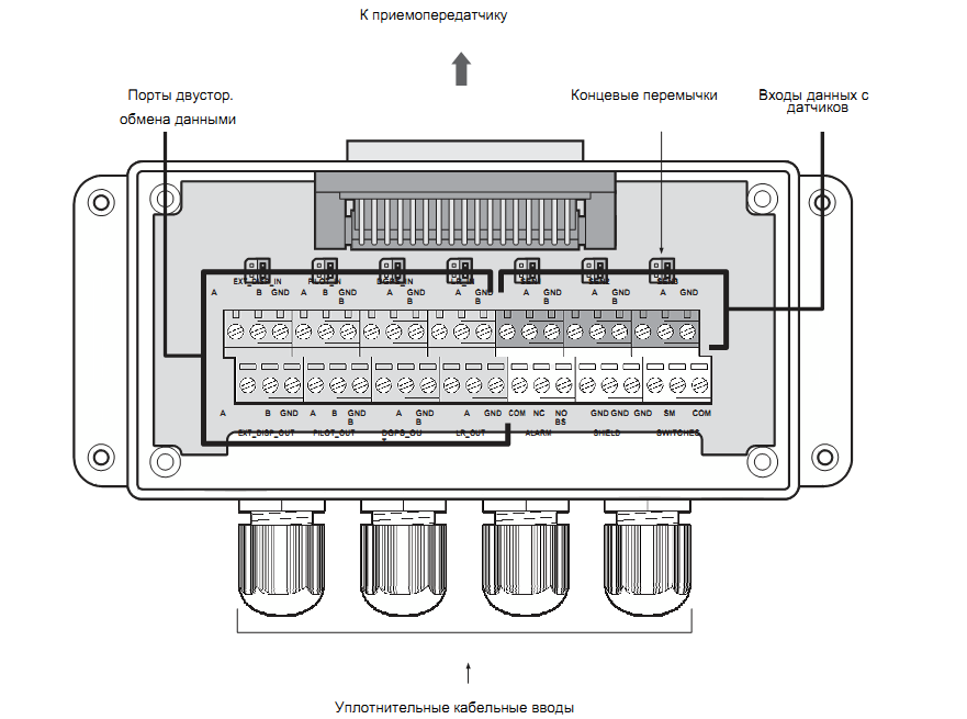
To connect an external device (computer or ECDIS, for example), the "External display" port is used.
IMPORTANT: When connecting several external devices, it is recommended to install the NMEA splitter to amplify the signal and prevent the failure of the port.
An example of connecting an external display is shown below in the figure. To determine the signal line "A" and "B"
ground. If the voltmeter shows a negative voltage, then the line on which the
measurement is taken belongs to the category "A", the positive voltage indicates a signal
line "B". If the voltmeter is not - simply connect to the device and check the correctness of the data arrival, if the data does not arrive - change the polarity.
![]()
for connecting data input from the remote equipment. The following
terminal configuration options are available:
- R terminal for 120 ohms, recommended for a cable longer than 10 m.
- RC 120 Ohm per volt. / terminal device at 1 μF. Not used.
- No terminal device is available, it is recommended for a short cable, the length of which is less than 10 m (if included).
jumper next to the data entry terminal in the terminal box. Jumper settings for each
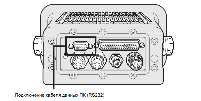
terminal version OPTION 2 There is a 9-pin D-shaped connector on the back of the T105 transceiver. This connector allows you to directly connect to the RS232 personal computer interface and can be used to install, diagnose or connect an external display. The default settings for this interface allow you to connect to the ECDIS or electronic card system and duplicate the 'External display' port of the terminal box.
The RS232 port is galvanically isolated from the input power source.
This means that no "extra" impact on your PC and back will not be. For example - without galvanic isolation, it is possible that when the sensor is connected, the mouse cursor randomly jumps over the screen.
Diagram of connection to the terminals of the D-type connector on 9 terminals on the rear panel of the
transceiver:
1 Not used
2 Transmission of RS232.
3 Receiving via RS232
4 Not used
5 Grounding RS232
6 Not used
7 Not used
8 Not used
9 Not used