Steering Gear Interface NAVIPILOT 4000+ / NAVIGUIDE 4000
13.04.2017
In accordance with the type of steering mechanism, additional control boards for the steering interface must be added to the system. The total number depends on the number of steering pumps or steering systems. Whenever USCG and / or US flag requirements are to be met, use interface cards with relays.
| code | name |
| 020040-0000-000 | AC Bang-Bang solenoid valve control panel for integration into the steering control unit |
| 020041-0000-000 | Control panel of the AC Bang-Bang solenoid valve (with relay) for integration into the steering control unit |
| 020042-0000-000 | DC Bang-Bang Solenoid Valve Control Panel for Integration into the Steering Control Module |
| 020043-0000-000 | DC Bang-Bang solenoid valve control panel (with relay) for integration into the steering control unit |
| 020044-0000-000 | Isolated proportional interface board for integration into the steering unit |
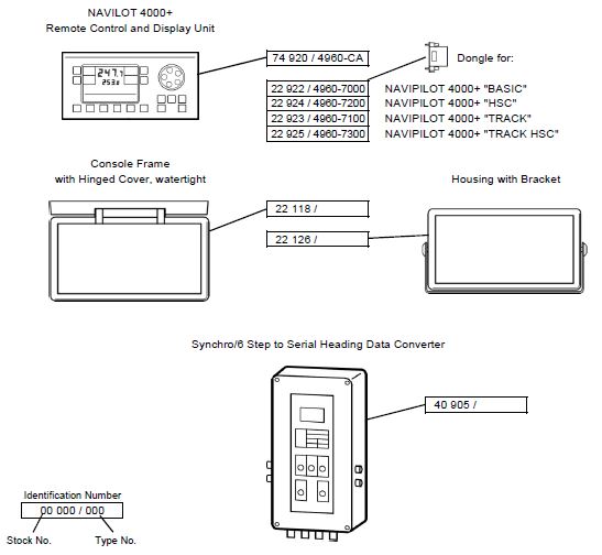
| 074920-0000-000 4960-CA |
Remote control and indication unit NAVIPILOT 4000+ with connecting cable (3 m), incl. one of the following keys, depending on the main autopilot system: 022922-0000-000 Dongle NAVIPILOT 4000+ BASIC, 022924-0000-000 Dongle NAVIPILOT 4000+ HSC, 022923-0000-000 Dongle NAVIPILOT 4000+ TRACK, 022923-0000-000 Dongle NAVIPILOT 4000+ TRACK, |
| 022118-0000-000 | Console frame with hinged cover for the NAVIPILOT 4000+ control and display unit for waterproof installation |
| 022126-0000-000 | Housing and brackets for the NAVIPILOT 4000+ control and display unit for desktop, bulkhead or ceiling mounting |
| 040905-0000-000 | Synchronous / 6-step serial data converter in the case for conversion / display of course data for connection to 24 VDC, supporting the following inputs: Synchronization of the course: 1: 1 or 360: 1, 10-115 V, 50-500 Hz 3, 6 and 24 steps / 1 °, 5-40 V DC (requires independent power supply) |
Control panel for steering interface
(for integration into the steering control unit)| AC Card | 2 sets of outputs, each with a port / Stbd. - 24-230 V AC Current, 4 A peak, 1 A max. hold - 2 "pump for" contact closure inputs (<1 Ω = on,> 100 kΩ = off) |
| AC board (with relay) | |
| DC Board | 2 sets of outputs, each with a port / Stbd. - 12-110 V DC Current, 2 A max. - 2 "discharge at the input of the contact closure sensor (<1 Ω = on,> 100 kΩ = off) |
| DC board (with relay) | |
| Isolated proportional board | 2 outputs for rudder or rudder error - ± 10 V DC, max. load 20 mA / 4.20 mA |
 +7 (812) 4-673-673
