+7 (812) 4-673-673
Factory acceptance tests
Commissioning is the process of getting the installed equipment to work properly and fulfill its functions. It is done in steps, starting at the manufacturer's workshop where the essential equipment is tested before it is transported to the shipyard. These tests at the makers are called Factory Acceptance Tests (FAT) and certify that the equipment performs properly, when leaving the workshop. Essential equipment includes generators, motors, switchboards and control gear assemblies, transformers, alarm and monitoring systems.
1. R otating machines
Generators and motors, usually identified as rotating electrical equipment, have to be subjected to a heat run test, to demonstrate that the rotating equipment can perform its duty within the temperature limits of the materials used. Heat run tests can be performed under actual conditions, under load with the same characteristics and cooling conditions as the expected load in service. It is often simulated by a no-load test and a shortcircuit test. The sum of the rise in temperature represents the actual temperature rise.
It is often limited to the electrical windings of a machine, but should also include mechanical parts such as bearings. In addition, megger tests, insulation resistance tests and high voltage tests as well as overspeed tests at 120% for two minutes, are carried out. If possible, load steps and other dynamic tests are run. If dynamic tests cannot be carried out in the workshop, they must be done during the harbour acceptance tests (HAT) or during sea trials.
2. Cables
Cables used onboard of ships must be type-approved, meaning that they have been subjected to a series of tests together with an approved quality assurance system of the manufacturer. These cables are listed in the type- approved equipment of the various classification societies. In general, these cables are specially designed and are suitable for conditions with respect to vibration. Thus, stranded conductors, fire retardant and low smoke and low halogen insulation.
3. Switch and control gear
Very few have type approval, but most switch gear and control gear assemblies have been built from type approved parts. All main and emergency switchboards must be factory tested to verify operational and insulation quality by Megger and high voltage tests.
The tests consist of checks of interlocks, synchronisation, autostart and autoclose of generators and circuit breakers, sequential restart, load shedding, depending upon the ship's specification.
4. Circuit breakers
Circuit breakers have to be adjusted and tested by the manufacturers. Certificates of required settings and test results must be submitted and verified. Nameplates must be fitted adjacent to the circuit breakers in the switchboard referring to the adjusted settings to enable replacement.
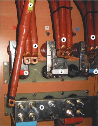
Cables temporarily disconnected for testing purposes
High voltage connection box:
2. Terminal L2
3. Terminal L3
4. Conductors LI
5. Conductors L2
6. Conductors L3
7. Earth conductor
8. Starpoint
5. Starting devices
Large starting devices (>100kW) must be tested at the manufacturer's workshop as far as practicable. The tests are more or less identical to the tests of switchboards.
6. Converting equipment
Large converting equipment (> lOOkW) must be tested at the manufacturer's workshop. For rotating converting equipment, the same tests are applicable as for rotating machines.
For static converting equipment, built from type-approved parts, functional tests have to be done simulating the performance of the converter and checking temperature rises of the approved parts in the assembly. This can be done during a full load test with the same cooling arrangements as in the ship's design standards.
This usually means cooling air of 45°C, cooling water, if direct seawater is used, of 32°C, but mostly freshwater through a heat exchanger of 37°C, or air, cooled by either sea or fresh water with maximum temperatures of 37 and 42°C respectively, allowing a temperature difference over the water/air heat exchanger of 5°C. Sometimes, if a chilled water system is installed, chilled water with a temperature of 6°C is used.
7. Transformers
Large transformers (> 125 kVA or lOOkW) with a power factor of 0.8 have to be tested at the manufacturer's workshop. The test must include a megger test, a high voltage test and a megger test again, as well as a heat-run determining the temperature rise of the windings at full load conditions.
Similar to rotating machines, often the test is done by a combination of a no-load test and a short-circuit test which gives a good idea of the temperature rise at actual load.
8. Automatic control systems
Large control systems, or better complicated control systems, have to be tested at the manufacturer's. This means building up the various components, such as equipment, control-stations and work-stations and connecting these, making it a complete system. It is more efficient to test a complicated system at the manufacturer's, as all control locations are close together and the changes of control positions are more easy to test. Transfer of control from one location to another shall be bumpless and accepted by the other location. This to avoid unacceptable surprises.
Failure of a power supply shall not cause change in control result or alarms only,
9. Alarm and monitoring systems
Alarm and monitoring systems must also be tested at the manufacturer's. These include simulation of alarms, checking of group alarms at the bridge, and of engineer's alarms.
Duty selection, safety timer for not accepting alarms, safety timer for one person on watch, automatic change over from unmanned to manned operation when accepting an alarm in the engine room, at the same time starting the safety timer to protect the engineer attending an alarm. Graphics and trending must also be checked during this factory acceptance test.
Also system failures have to be tested. Thus, main power failure with alarm only, back-up power failure, communication failure of distributed systems and cable failures. Printed circuit board card (PCB) failures must be restricted to that part only. Alarms have to indicate the location of the fault.
10. Dynamic positioning systems
Dynamic positioning systems vary from simple computer assisted systems with Notation AM, via redundant systems Notation AA, to fully redundant systems Notation AAA. For the more complicated systems, a failure mode and effect analysis (FMEA) has to be made, identifying the consequences of all possible failures. This is the basis for the test procedures. The functional tests are more difficult to simulate. As most of the systems have to be adjusted to the characteristics of the ship, especially for the first ship of a series, these are usually done during sea trials.
11. Systems in general
It should be clear that all factory acceptance tests have one common purpose: that is to confirm the suitability of equipment to be installed onboard. Every step in the FAT testing programme has one major purpose. This is to ensure performance during the harbour acceptance tests (HAT) and of course, during the final acceptance test, the sea trials. Consequently, the above testing must be executed with all new and essential equipment or systems working.
12. EMC/THD tests
All navigation and nautical equipment has been tested for electromagnetic compatibility during the type approval procedure. Interference between components should not exist as long as all equipment is installed in the original housing and in accordance with the instructions of the manufacturer.
When in the open deck area other sensitive equipment is installed, such as a frequency converter operated deck crane, controlled from a control cabin with many windows in view of the radar antenna beam, also this control cabin has to be tested for EMC.
Measuring the Total Harmonic Distortion (THD) for different operational conditions is particularly advised when large Variable Frequency Drives are installed. These measurements are sometimes also required by Class.
13. Step loads
After testing of the individual diesel generators for proper operation the sets are tested in parallel operation. With 3 sets, first 1 and 2 in parallel, thereafter 2 and 3 and finally 1 and 3. When current and kW loadsharing is in order the engines and generators have to be subjected to step loads.
A step load is a suddenly applied load on the generator, to check the performance of the generator AVR as well as the diesel governor. Usual steps are from 25 to 50 % and 50 to 100 %, whereby the minimum voltage and the minimum frequency during the process have to be checked.
Another test of the diesel and generator performance is the switching off of a certain load whereby the overvoltage and maximum frequency of the sets are checked during the process. This is usually done in parallel, operating by switching off circuit breakers.
14. Example of EMC interference
EMC interference problems are sometimes hard to trace like in this example of an Offshore Construction Vessel. When the ship got operational it appeared that the crane would not work although this had been succesfully tested during harbour trials. It took a long time to find the reason for this failure of the crane but in the end it appeared that the beam from the radar disturbed the crane controls. By screening some cables in the control cabin of the crane the problem was solved.
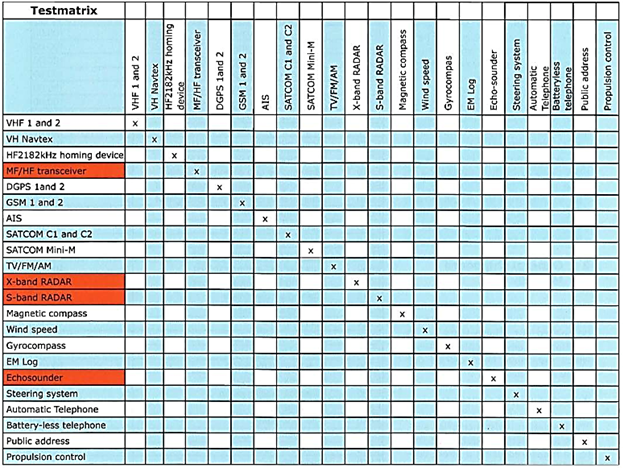
The test matrix for commissioning should include verification of this sort of interferences.