 +7 (812) 4-673-673
Transformers
General
The simplest converter is a transformer, transforming or converting one voltage into another voltage, for instance 440 V into 110 V.
Transformers have losses, as heat is produced during this conversion. The efficiency is usually between 90 and 98 percent, depending on size, a reason to avoid transformers in power distribution systems. The European 400V/230V 3-phase 4-wire distribution system does not require transformers, contrary to the American 450V60Hz sytems which have a phase to neutral voltage of 260 V. For the latter systems no equipment is standardized, being the reason that in the USA where 110 V/60 Hz or 230 V / 60 Hz is used (onshore) for small consumers, transformers are necessary for lighting and low power circuits.
The multiplication of input voltage and current and output voltage and current is approximately equal. More complex converters can also change voltage from AC to DC and can also change the frequency.
Small converters are used to adapt the power voltage to another system, such as a 400V signal into a 10V or 20mA signal. A transformer consists of two windings around a metal core. The primary windings magnetize the core, which induces a voltage and current in the secondary winding. Any voltage ratio can be obtained, but is dependent on the winding ratio of the primary and secondary windings.
With separated primary and secondary windings there is also a galvanic separation between the primary and secondary circuits. In that case an earth fault detection system must be installed on the secondary side. Every isolated system is required to have this as per Class requirements.
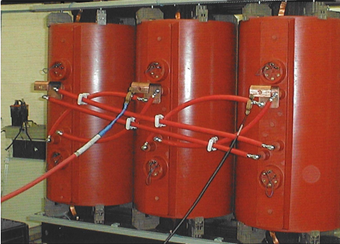
Double stock 1600 kVA transformer, for supply of a frequency converter,
during high voltage testing.
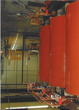
The rear side of this transformer can be seen below.
Secondary windings produce voltage in star and delta configuration.
The red cables are the connections of the primary windings.
The secondary windings still have to be connected
Short-circuit currents for transformers are determined by the short-circuit voltages of the transformer, defined as: 'the voltage applied at the primary side of the transformer with the secondary side short-circuited resulting in the full-load current primary'. The maximum secondary short-circuit current at the secondary side is then determined by:: Ik(sec) =Unom / Uk x Inom(sec)
Three single-phase transformers in one housing makes a cost effective three-phase transformer. By adding a fourth single-phase transformer in the same housing as spare, creates redundancy as this fourth transformer can be used to replace a faulty transformer quickly by just reconnecting wires.
Auto-transformers, i.e. transformers with a single winding, are only acceptable for start circuits and not for distribution systems. The reason for this is that a failure of the starpoint connection would result in full primary voltage on the low voltage circuits.
Especially large transformers may have a high inrush current due to the build-up of the magnetic field in the steel cores. To avoid this inrush current, which may trip the circuit breaker in the supply, a small premagnetising current is applied for a couple of seconds.