 +7 (812) 4-673-673
Technical factors affecting the radar image
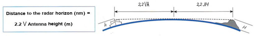
An antenna sited at 4 meters height gives a radar horizon of 4.4 nm. Only objects that project above the radar horizon will be detected by radar. Even radars that have impressive range specifications will only detect tall objects. Raising the height of the antenna has only a limited effect. An increase from 4 to 9 meters moves the radar horizon from 4.4 to 6.6 nm.
Refraction
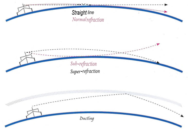
Layering in the atmosphere can refract radar energy and weather conditions can do the same thing. The result is to either increase or decrease the distance to the radar horizon.
Sub-refraction occurs when the temperature of the air is lower than that of the sea under it. Sub-refraction tends to decrease the radar horizon while super-refraction, which is associated with stable high pressure weather, does the opposite. A warm, moist body of air over cold water will cause the radar energy to refract more than usual, thereby following the surface of the earth. This causes the radar range to increase. An even greater range increase will occur when the radar energy is repeatedly internally reflected between an atmospheric layer and the sea surface ("ducting").
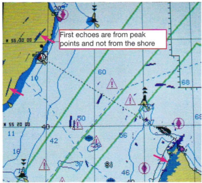
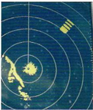
A radar overlay on an electronic chart of the Bornholm channel. The echo of some of the highest hills is visible somewhat inland on the mainland (Scania). The echo of the high part of the adjacent Bornholm is seen on the coastline
1. The radar lobe
In order for the radar to register a target on a correct bearing its energy must be propagated in a narrow sector: the narrower the sector, the sharper the image. This sector is called the radar lobe. The energy requirements increase as the width of the lobe is decreased so smaller radars have to make a compromise. Really big radars equipped with long antennae can propagate within a sector subtending less than 1°, while a small radar on a leisure vessel, equipped with a short antenna, has a sector subtending about 6°. A broader lobe results in a poorer accuracy of bearing measurements. To enable the radar to produce an image even when a vessel is heeling, the vertical extent of the radar pulse is usually about 30°.
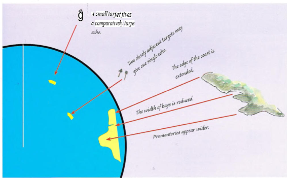
An effect of the lobe width is that small targets will appear disproportional large, points appear broader and bays narrower or indistinguishable. The target begins to reflect an echo as soon as the leading edge of the lobe reaches an edge of the object. Energy is reflected continually until the trailing edge of the lobe has passed the object. The result is that small objects such as buoys give a banana-shaped image which is disproportionately large in relation to the actual target.
The rotational speed of the anterna (20-60 r.p.m.) has an effect on the lag of the image on the screen during a turn. Fast vessels in narrow waters need a fast rate of antenna rotation. The speed should be low enough so that small targets will be hit by several radar pulses at each scan of the antenna.
Common effects related to pulse width
2. Pulses
A good target will reflect the leading edge of the pulse and continue to give an echo for the entire length of the pulse. A longer pulse contains more energy. The pulse length is automatically coupled to the range scale, although some sets have an optional manual override. There are three types of pulse length: short pulse (SP), medium pulse (MP) and long pulse (LP). At short ranges one wants to use short pulses in order to get a sharper image and to improve discrimination of targets that are in line.A puls can be as short as 50 nanoseconds (10"9 seconds) for short ranges. For long ranges more energy is needed and the puls may be about one microsecond. The energy is produced by a magnetron which is powered by extreme hight voltage. New technology for radars uses solid At really close range one can observe the effect of pulse length when passing a mark, such as a spar, whose echo will then be extended radially. Radar sets automatically change the pulse length when changing range. On some radars it is possible to choose the pulse length manually.
The closest range at which a modern radar will give an image is something around 25 m. This is even closer for broadband radar. Below the closest range no image will be displayed.
The time between pulses is long compared to the length of the puls, which mean that the average power is quite low. The Pulse Repetition Frequency (PRF) varies with different ranges and can be from about 350 to 3000 pulses per second.
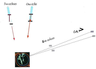
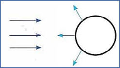
Two targets in the same direction give one echo if the distance between them is less than half the pulse length, because the leading edge of the second echo will overlap with the trailing edge of the first echo. (Blue arrow = transmitted pulse. Red arrow = reflected pulse.)
When the pulse width is wider than the distance separating two targets then the two objects will return only one echo. This is a function of both pulse width and distance. At short range the pulse width is smaller and then the targets will give separate echoes.
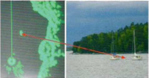
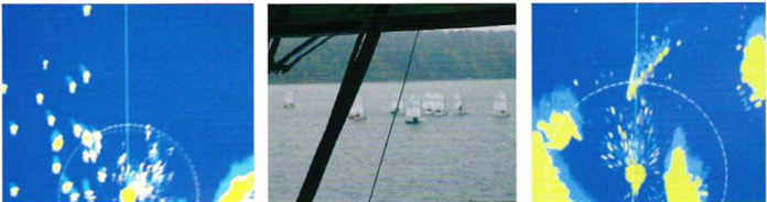
These two boats give only one echo, located fine on the starboard side of the heading line
The frequensies used by marine radars are 2,9 - 3,1 GHz, (S-band) and 9,3 - 9,5 GHz (X-band). Approximate wavelength 10 cm and 3 cm respectively. The 3 cm radar are more sensitive than 10 cm. Which
mean that 3 cm can show more small targets, but is also more blurred by echoes from rain, snow and waves, later explained. The reverse is guilty for 10 cm. So it is an advantage to have one of each.
4. Radar shadow
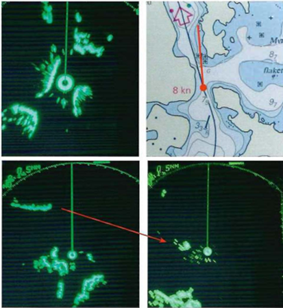
The contours of land as seen on the radar screen may have only an approximate resemblance to the coastline as drawn on the chart. Objects behind and lower than another target will not be displayed. In
the picture to the right, the position of the vessel is shown by the red dot on the chart. When interpreting the image it is important to allow for the fact that radar will not register objects that are shadowed or low-lying. This is why the coastline in the radar image is not a continous line.
Another consequence of this is that the echo of an island can change shape as the vessel passes it and the radar registers it from different directions. See the images to the right of the long island on the
port bow of the vessel: long when seen at an angle, short when seen head-on.
Closing the coast. Piers and houses are good radar targets, as they are hard and have marry small angles that reflect the radar pulse
A racon (see picture on the left) is a special radar "lighthouse" that transmits signals on the radar frequency. On the screen this gives a special echo. The chart gives information about the specific character of the signal transmitted, expressed as short and long lines. Note that a racon signal may not register on every sweep of the antenna. Broad-band radar does not trigger racon signals.
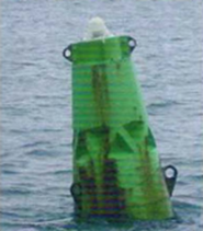
A light buoy with built-in radar reflector> consisting of tetragonal depressions whose sides are oriented at 90 degrees to each other. This construction always reflects some of the pulse back to the receiver, no matter from what direction it arrived.
5. Target quality
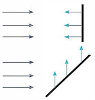
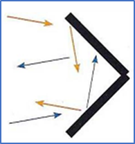
A large, flat, smooth, hard surface gives a strong echo when radar pulses strike it at a right angle: these conditions are met by the side of a ship's hull or the front of a building. At other angles more or less of the energy is reflected away from the receiver and the echo will be weaker. In practise, ships, buildings, piers and so forth always give echoes as there are numerous irregularities, some of which will reflect the pulses towards the antenna. Factors that affect the strength of the echo on the screen are:
- Material (electrically conducting materials give better echoes than insulators)
- Size
- Height
- The angle of the surface to the radar energy
- The shape and structure of the surface
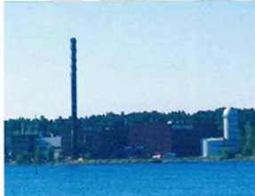
Tall cylindrical objects, such as a chimney or a cistern, give a good echo because the radar lobe has a height component Although much of the radar pulse is reflected away, a small vertical area is always normal to the pulse.
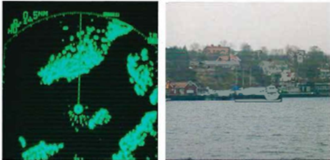
Bigger ships are excellent radar targets as they have extensive hard surfaces with many angular structures, so they give echoes a long way off. In the picture on the right the echo of a vessel can be seen fine on the port side of the head line.
In tidal waters the radar image can vary considerably between high and low water. At low water large areas of drying sandbanks will give weak or no echoes as the smooth sloping surfaces reflect much energy away from the antenna.
|
At close range even small boats may give echoes, as shown in the pictures above |
In the picture above the wake of a fast motorboat can be seen, as well as the after-glow of the echo. The extent of the after-glow can be tuned using the TRAIL (sometimes TAIL) button to adjust a time factor |
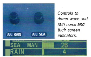
Always begin to adjust the display on the screen by zeroing the controls for RAIN and SEA (RAINCLUTTER, SEACLUTTER). These controls are used to remove noise from rain and waves in the echo, but they also damp interesting echoes, so initially they have to be zeroed.
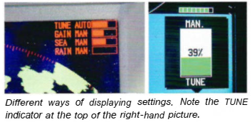
Go now to TUNE, which tunes the receiver with the transmitter. Most modern radars tune themselves automatically and on some sets one can change between automatic and manual settings. When tuning manually it is necessary to sweep backwards and forwards with the control to find the optimal setting. Adjust TUNE so that it gives a maximal intensity on the indicator
Now turn up the GAIN (image amplification) strength. Now if not before an image will show on the screen. The correct GAIN setting depends on what the Navigator wants to observe. In confined waters a low GAIN setting will give sharp coastlines whereas a higher GAIN is useful in open water where long range is desirable. Using this GAIN setting when entering a channel will give too strong echoes from the shorelines and the image of the channel may become completely obliterated by the strength of the echo.
It will usually be necessary to fine-tune all the controls once the set has warmed up. GAIN and TUNE are used in conjunction, fine-tuning first one and then the other, perhaps more than once. What is "right" at any given moment depends on what the Navigator wants to see just then!
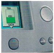
The GAIN control on this menu-controlled radar is activated with the button under the window and is regulated by the touch pad on the right
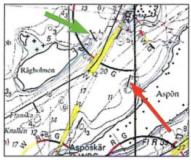
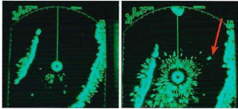
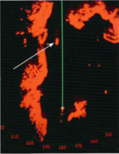
The upper left image shows a screen with a low GAIN setting. The image to the right is dominated by echoes of waves close to the ship. As the GAIN was increased the echo of a navigational mark became visible. This is seen on the chart image (to the left, red arrow). Another mark (green arrow on the chart) has not yet been displayed on the radar screen
The response of controls on radar sets from different manufacturers can be rather different. TUNE may require only 2 fine adjustment on one set, but may need large adjustments on another set. The same thing is true for GAIN, some sets give an image with a gain at its minimum setting, in other kits it should be set much higher.
All radar installations have a device for changing the SCALE (RANGE). This is the distance at the sea surface, which corresponds to the distance from the center to the edge of the image. When navigating in confined waters, adjustments must be made frequently to detect important echoes. This includes changing the scale. Longer range for finding information near rudders and shorter range for checking the immediate surroundings of the vessel. A common mistake when swimming in confined waters is to use too long a short range - you have to switch back and forth!Changing the scale by turning the knob is the easiest way to change the range, but there may be plus and minus buttons.
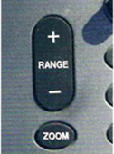
| Information in the righthand upper corner; Plus/minus buttons for scale changes. Below this, pulse change button, etc.. |
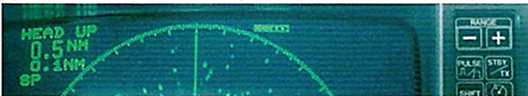
Information in the left-hand upper corner: mode = HEAD UP. Scale = 0.5 nm. Distance zetween the fixed rings = 0.1 nm. SP = SHORT PULSE |
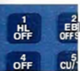
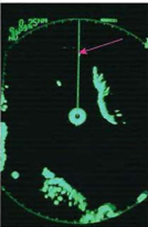
HEADLINE MARK (HM) or HEADLINE (HL) is a line from the center of the image in the direction that the bow of the boat is pointing. It is always visible, unless you turn it off with the button in manual mode. This is done when searching for a target that may be hidden by the HEADING LINE. This is normally only a need at long range when the echo of an approach lighthouse may be weak. The picture on the right shows a weak echo just touching the HEADING LINE. This would be clearer if the HEADING LINE was suppressed for a moment or two.