 +7 (812) 4-673-673
Rate gyro
Rotating gyros that are not North-seeking are called "rate of turn gyros" Unlike North-seeking gyros these have two instead of three degrees of freedom. Autopilots use rate of turn gyros to automatically
steer the ship and show the rate of turn (ROT). They are only used over shorter distances as they don't keep their orientation in space over extended periods of time.
IMO accuracy demands for rate of turn instruments:
- he indicated rate of turn should not deviate from the actual rate of turn of the ship by more than 0.5 degrees per minute plus 5 per cent of the indicated rate of turn of the ship. These values include the influence of earth rate.
- Periodic rolling motion of the ship with an amplitude of ±5°and period of up to 25 seconds and periodic pitching motion with an amplitude of ±l°and period of up to 20 seconds should not change the mean value of the indicated rate of turn by more than 0.5°per minute.
- The ROT instrument should meet these accuracy requirements at all ship speeds up to 10 knots.
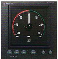
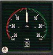
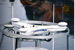
Rate of turn gyro with operator panel and a repeater that shows the rate of turn, ROT. (Raytheon Anschutz)
Ring Laser Gyro
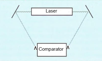
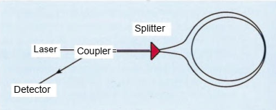
In order to detect rotation of the instrument, the Ring Laser Gyros (RLG) uses mirrors to reflect laser light. The laser beam is split, so that one beam is directed clockwise and the other anticlockwise. They are then refleced by mirrors. When the device is not rotated the two beams will reach the comparator without phase difference. But when the device is rotated the laser beams has to travel different distances to travers the circuit. This difference is detected by comparing their phases and the rotation can be measured. This function is based on the so-called "Sagnac" effect.
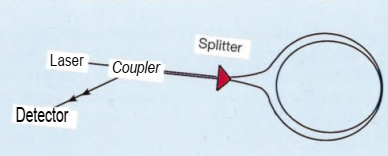
A Fibre Optic Gyro (FOG) uses a similar concept to the Ring laser gyro, but a fiber-optic coil is used as a very sensitive rate sensor.
The input laser beam is split into two beams that travel the same path but in opposite directions: one clockwise and the other counter-clockwise.
When a rotation is applied, the optical path for one beam becomes slightly longer while that of the opposing beam becomes shorter producing Sagnac frequency shifts.
A combination of three such fiber-optic coils (gyroscopes) and a dual-axis electronic level sensor is able to determine the direction of true north.
This system has no gimbals, no moving parts. The Fibre optic gyro will not have any speed,- or ballistic error, but a small error that increases with increased latitude.
When the Gyro is not rotating, the distance travelled by the light are of equal length in both directions, and no phase difference will occur.
When the Gyro is rotating, the distance travelled the different ways are not equal, and the detector can detect a phase difference. The FOG translates this into a measurement of rotation
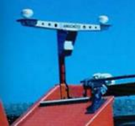
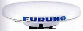
The satellite compass
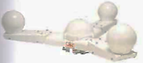
The satellite compass measures the course of the vessel by comparing the phase difference between the carrier waves of the different satellites. This requires that the special antenna receives sufficient data
from satellites: some compasses need at least 6 satellites for this purpose. Satellite compasses may have up to four antennae. From the signals received the instrument can calculate several parameters:
- Heading
- Rate of turn (ROT)
- Course over Ground (COG)
- Roll and pitch
If the signals are cut off by, for example, bridges, or in canals or harbours then the reserve system of the compass will take over the business of calculating the course for a short time, or until the signal returns. The reserve system consists of a solid-state sensor for the earth's magnetic field. High-quality satellite compasses have an Inertial Measurement Unit (IMU) as a backup. This consist of three turnsensitive sensors and three accelerometers. The quality of the back-up system determines for how long the data that it supplies can be relied upon.
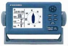
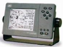
The development of satelli compasses is aimed at presenting more and more data
Sources of errors
- Random errors may be introduced depending on the distance between the antennae and on the number of antennae that the compass uses. A GPS compass with four antennae and a relative distance between them of 3 meters has an accuracy of 0,05°. With three antennae and a relative distance of less than 1 meter the accuracy will be between 0.25° - 0.4°. The most common satellite compasses have only two antennae.
- The so-called A-error is a constant depending on not being mounted in the fore and aft line direction. The installation should also minimise multipath effects.
- If the compass is not receiving a sufficient number of satellite signals then no course will be shown. When this happens the reserve system will take over for a short period.
GPS compasses have not been approved by the IMO as a replacement for magnetic or gyro compasses.