 +7 (812) 4-673-673
Maintenance
Maintenance onboard modern ships has to be planned very carefully. The required checks and tests are spread over the total maintenance period.
1. General
A Failure Mode Effect Analyses which is a requirement for the higher classes of DP-notations also provide insight into the effects of single failures and methods to prevent unwanted consequences. Monitoring and collecting data of failure, parts involved, alarms prior to the failure, help to improve planned maintenance.
To aid maintenance, more and more ships have computer systems on board for remote monitoring and life cycle management.
Such a system is linked to the alarm data computer memory, coupling the type of alarm to the running hours of the relevant item, in order to generate maintenance planning. By means of satellite communication equipment suppliers can monitor equipment on board and advise the crew or materials can be ordered to be available in the next port of call.
2. Rotating machines
2.1. Air-cooled machines
Special attention for loose fixings of wires between rectifiers and windings on poles.
General cleaning when found dirty inside. Grease (roller) bearings as per maker’s instructions.
2.2. Water-cooled machines
As 2.1 air-cooled machines. In addition, the testing of the cooling water leakage detection and alarm.
2.3. Large machines with sleeve bearings
Check the circumferential clearance of the rotor in the stator. Register data and check bearing clearance and lubrication system
2.4. Machines with roller bearings
Roller bearings have to be greased as per maker’s instructions.
2.5. Insulation resistance
Measure insulation resistance and register data and conditions, i.e. warm after running, and/or cold after a longer period of standstill.
2.6. Slip rings and brushes
Visual inspection to check for scratches and excessive brush wear
3. Cables3.1. Cables in hot areas
Visually inspect cables routed in hot areas, look for colour changes due to overheating of wires. Replace cables by heat resistant types if necessary.
3.2. Cables in dangerous zones
Inspect cables for damage of outer sheaths. Repair if possible to avoid corrosion of metallic braiding underneath. Check glands of certified safe equipment for tightness.
3.3. Insulation resistance
Measure insulation resistance of all cables in safe areas. Measure all outgoing groups of the power distribution system, inclusive of consumers. Use megger-list as provided at new building for reference.
4. Switchgear4.1. Visual inspection for dirt
Cleaning or replacement of air filters, visual inspection of connections for discolouring of wires by overheating, visual inspection of bus-bars.
4.2. Visual inspection movable connections
This is applicable to tulip contacts of withdrawable circuit breakers and starters. Check for proper working springs, if not accessible carry out conductivity tests.
4.3. Thermal photography
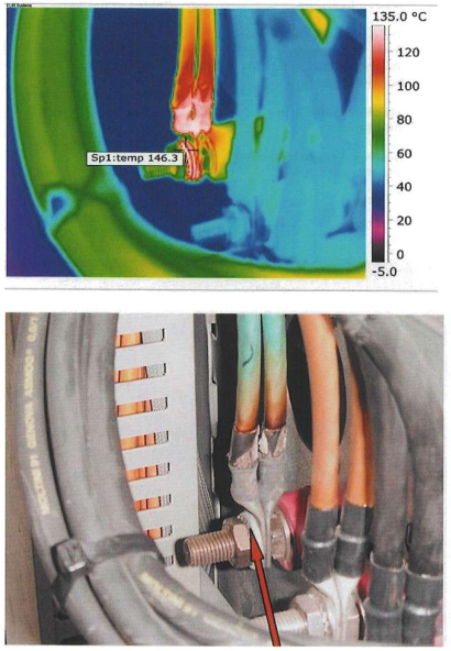
Thermal photography with an infrared camera is a quick way to find bad connections. It has to be carried out with the circuits under load or shortly after having been under load. When a hot spot is found, also a colour image has to be made of the same location to identify the hot spot. Some thermal cameras adapt the scaling of their pictures to the hottest spot in that picture. So a bright yellow part can be 35 °C in one picture and 135 °C in another. Some switchboards have not sufficient access to photograph all possible hot spots. Those switchboards also have to be visually inspected after switching off and opening of the doors.
See pictures below.
4.4. Bus-bar connection conductivity and insulation resistance
Bus-bar connections are made with steel bolts, nuts and spring washers. Bus-bars can have a temperature of 125° centigrade under full load. Locking nuts with PVC or nylon locks have to be suitable for this temperature. Nuts to be fastened with a torque wrench to avoid overstressing of the copper. Overstressing above the yield stress of the copper results in loose connections. Checking all the connections in a switchboard bus-bar system with a torque wrench is a lot of work, not to mention the opening and closing of the bus-bar compartments.
Another way to check these connections is to measure with a low resistance measuring device from one outgoing group at the cable connections to the second outgoing group at the cable connections. Followed by the second to the third and so on. With all circuit breakers open the insulation resistance of the bus-bar system can be measured.
5.1. Low Voltage
Most LV circuit breakers are air circuit breakers with main contacts, arcing contacts and arc extinguishing chambers. Arc chambers to be taken off and inspected for debris. Arc contacts and main contacts to be inspected for damage. Interval time annually or after clearance of a serious fault.
5.2. High Voltage
Most HV circuit breakers are either gas filled or vacuum and cannot be opened for contact inspection. There, with the same current injection set as used for the bus-bar conductivity tests, the resistance in micro-ohms of the closed contacts can be measured.
5.3. Functional tests
Check the circuit breakers in the test position for correct closing and opening. Check remote conynchr and check the ynchronizing mechanism (closing at the correct moment by the ynchronizing device as observed by the Synchronoscope).
5.4. Calibration of protection devices
Calibration of protection devices such as over-current, short-circuit current, under voltage trip, reverse power, differential protection and their timing requires special tools and specialists. The interval between tests is usually five years.
6. Starting devicesStarters to be visually inspected for cleanness and cleaned if necessary. Also inspection for hot spots: - low voltage - high voltage - choke type - autotransformer type.
7. Converting equipment7.1. Air-cooled
Cleaning or replacement of air filters, visual inspection of windings, visual inspection of connections, checking for hot spots.
7.2. Water-cooled
Cleaning of heat exchanger, testing of leakage alarms, visual inspection of windings, visual inspection of connections, checking for hot spots.
7.3. Electronic components
Sensitive electronic devices such as printed circuit boards (PCB’s) in rectifiers and converters must be kept clean of dust, salt deposits, and checked on a regular basis.
8. Transformers8.1. Air-cooled
Cleaning or replacement of airfilters, checking of fans, if any, visual inspection of windings, visual inspection of connections, checking for hot spots.
8.2. Water-cooled
Cleaning of heat exchanger, testing of leakage alarms, checking of fans, visual inspection of windings, visual inspection of connections, checking for hot spots.
9. Emergency generator
Automatic starting on the first starting arrangement by simulating no-voltage of the feed from the main switchboard to the emergency switchboard has to be tested.
This is a time-consuming process, as pressures, temperatures and flow have to be simulated.
Analogue transmitters are easier to check: with an engine stopped, all actual temperatures are indicated at the engine temperature panel, or the preheating temperature of the motor.
With running engine bearings, pressures and temperatures can be compared and faulty sensors are easily found. Same goes for exhaust gas temperature transmitters, from no load to full load all of them should indicate temperatures in the same range.
The list of inputs as from the commissioning shall be used as a reference.
Batteries are to be checked for:
- correct liquid level
- corrosion-free connections
- cracks in the housing.
As the battery capacity is related to the ambient temperature the environmental conditions must be checked on a regular basis and through the seasons, especially during winter time.