 +7 (812) 4-673-673
EMC planning
The following describes how to build up an EMC plan for a customs patrol vessel, with a complete nautical and navigation package as well as a hydraulically driven bow thruster.
1. General project information
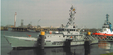
This ship is a modern high speed patrol and rescue vessel with a semi-displacement hull for coastal and offshore services. The patrol craft is built with a steel hull and an aluminium superstructure.
The propulsion system consists of two electronically controlled common-rail diesel engines driving controleble-pitch propellers. The electric installation 400/230V 50Hz 3 phase 4-wire neutral earthed is powered by two electronically controlled common-rail diesel generator sets. The bowthruster is hydraulically driven. All engines are electrically started from batteries. Emergency power is also from batteries.
2. Definition of EMC
Electromagnetic Compatibility (EMC) is the ability of equipment and/or combinations of equipment to function properly together as well as within the ship's environment. Type-tested electronic and electric equipment is tested by a certified testing laboratory in order to be certain that it will function properly in the expected ship's environment.
Requirements for type-tests can be found on the web sites of the classification societies as well as International standard IEC 600945 and IEC 600533. Parts of these tests are related to EMC and are also related to the disturbance of low level emergency transmission signals such as VHF signals in the 156-165 MHz range. For more extensive definitions of EMC see IEC 533 electromagnetic compatibility onboard ships.
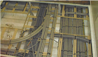
Power and control cables in a double floor
3. General arrangement plan
This plan is used to achieve the first impression how to start with EMC. It helps to derive the guidelines and recommendations for technical measures to achieve electromagnetic compatibility in ships and of ships' equipment. These preventive measures concern electric and electronic equipment and in special cases, non electric equipment. The following general measures are applicable to EMC:
a. Decoupling
b. Reduction of the interference level at its source
c. Increase of the susceptibility level of the affected equipment or system.
4. Decoupling
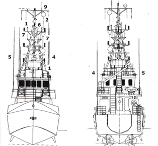
Space is limited in ships, especially in small ships. The installation of equipment in an other space or at sufficient distance from each other to prevent interference, is difficult. To find the best compromise for the location of radio and navigation aerials, a listing of the aerials in sequence of importance is made and then a suitable position is found. Aerials do interfere when fitted close to each other.
In order to ensure proper television reception, it is advisable to install the omni-directional television aerial above the everyday working VHF aerials.
5. Reduction of interference level at its source
After having established the location of the different aerials, the effect on the equipment onboard has to be determined.
Then the distance to the other equipment has to be considered and the measures defined.
The first source of interference is the outside environment, such as other ships or shore-based ship guidance systems.
All equipment located in the above deck zone must be suitable for an EMC environment according to IEC 801-3 frequency range 27 MHz-500 MHz field strength level 10 V/m.
Near ship's aerials these levels are far exceeded, for example:
- A 1.8 metre rod aerial connected to a 40 W 40 MHz VHF transmitter creates a field strength of up to 59 V/m at 1 metre, reaching the 10 V/m at a distance of 3 metres
- A 3 cm X-band 7 ft navigation radar antenna connected to a 25 kW 10 GHz radar transceiver creates a field strength of 57 V/m, reaching the 10 V/m at a distance of 128 metres
- Naval communication and radar systems create field strengths of multiples of the above figures, reaching the 10 V/m value miles away.
6. First source of interference
The environment is the first source of interference with signals originating from other ships and shore systems. This environment has been defined in standards. All type-approved equipment fulfills the standard and is suitable to operate in the ship's environment.
Outside the ship's structure the signals are stronger than inside the metal structure.
The environment can be divided into:
- below deck zone.
Due to the large window area, the wheelhouse is considered 'above deck zone'.
Cables running in the 'above deck zone' act as aerials and transport the signals into the 'below deck zone' and to other electronic equipment. To avoid this, all outside cables must either be run in galvanized steel pipes or be screened. This screen has to be earthed at both ends, preferably as close as possible to the location where the cable enters the steel structure.
7. Second source of interference
The second source of interference is the system of cables within the steel and aluminium structure, transporting all sorts of signals through the ship. The type of signal transported through a cable determines what type of cable has to be used and the group to which the cable belongs:
(This is the basic matrix linking signals to measures. Every application has to be provided in detail.)
Group 1 - indifferent
Normal non-screened cable
- Power circuits
- Lighting circuits
- Control circuits
- Analogue and digital data signals
- Approximate signal range:10 V - 1000 V DC 50-60 Hz 400 Hz
Group 2 - sensitive
Single-screened cable, additional twisted pairs
- PLC interfaces
- Reference voltage signals
- Low level analogue and digital data signals
- Approximate signal range: 0.5 - 115 V DC, 50-60 Hz, audio-frequency
Coaxial cables
- Microphone signal
- Video signal
- Approximate signal range:10 |jV - 100 mV across 50 - 2000 Q DC, audio frequency to high frequency
Group 4 - extreme jamming
Coaxial cables screened power cables
- High powered pulse signal cables
- High powered semi-conductor converter cables.
To keep the coupling between the cables small, all lengths must be as short as possible. In order to avoid interference between the cables of the different groups these must not be run close together for longer lengths and a separation distance must be used. Also, the distance between the steel or aluminium deck or bulkhead must not exceed the figures from the table below.
Example of separation distance in cm to be maintained between cables of several groups.
|
|
Maximum distance cable to cable (mm) |
Max. distance from metal surface |
||
|
GROUP |
1 |
2 |
3 |
4 |
|
1 |
0 |
5 |
10 |
10 |
|
2 |
5 |
0 |
5 |
15 |
|
3 |
10 |
5 |
0 |
20 |
|
4 |
10 |
15 |
20 |
20 |
Cables terminating in one piece of equipment do not require separation from each other.
Screened cables
- Screened communication cables must be constructed with a copper wire braiding with a braided earthing lead of tinned copper wires underneath.
Earthing
This connection should be close to the glands or cable transits to ensure that the connection of the cable's earthing leads is as short as possible
- The earth connection to the steel or aluminium structure of the ship must also be as short as possible
- Earthing screens of power cables have to be earthed on both ends
- Earthing screens of sensitive cables only have to be earthed on the end where the signal is used
- Earthing of aluminium superstructure to steel hull has to be done at the joint.
8. Third source of interference
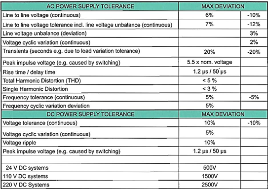
The third source of interference is the power supply system. Again, the following is the basic standard which must be detailed for the specified project.
The project power system supplies a three-phase four-wire neutral earthed system with two diesel driven generators. Neutrals are earthed in the generators. The generator circuit breakers have four poles. All equipment is also adapted to the "mechanical" aspects of a ship's environment with respect to temperature, ship's movement and vibration.
This supply system is very similar to onshore industrial installations. Standard industrial frequency converters with standard filters limit the harmonic distortion to acceptable levels as defined below. All equipment must function correctly when supplied from an AC power supply system with the following characteristics:
9. Increase of the susceptibility levels
Remote control and automation systems are often distributed systems, with intelligent local units, with suitable filtering and limitation circuits, to allow non-screened cables for digital input and output.
The data communication between the local units and the workstations must be performed with screened cables and routed separately from power cables.
Data communication has to be installed using coaxial cables or the signal has to be amplified to such a level that the susceptibility levels exceed the interference levels from the power cables. In that case no separation is required.
This solution can also be used when, during Harbour Acceptance Tests (HAT) and Sea Acceptance Trials (SAT), unexpected interference is found
Дистанционное управление и системы автоматизации – зачастую распределенные системы, с «умными» локальными устройствами, снабженными фильтрующими и ограничивающими цепями, чтобы можно было использовать неэкранированные кабеля для цифрового входа и выхода.
Обмен данными между локальными устройствами и рабочими станциями должен осуществляться экранированными кабелями, проложенными отдельно от силовых кабелей. Обмен данными должен проходить по коаксиальным кабелям или же сигнал должен быть усилен до такого уровня, что порог чувствительности превышает уровень помех от силовых кабелей. В этом случае не требуется сепарация.
Это решение также можно использовать, когда во время приёмных испытаний в гавани (Harbor Acceptance Tests, HAT) и в море (Sea Acceptance Trials, SAT) обнаруживаются непредвиденные помехи.
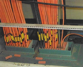
Cables directly into the structure to reduce interference
10. Communication and navigation equipment:
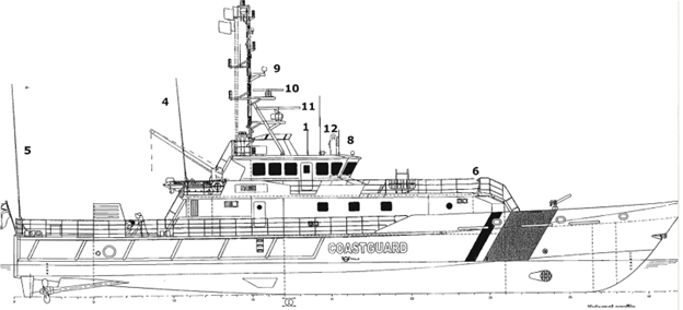
1. VHF 1 and 2: Cell wave CX4 radio telephone with DSC:
VHF aerial separated from DSC aerial, transceiver cable coaxial and routed separately from receiver cables.
1. VHF NAVTEX receiver: receiver cables coaxial.
2. HF 2182 kHz homing device: receiver cables coaxial.
3. MF/HF receiver unit receiver aerial shielded from transmitting aerial, receiver cables coaxial and routed separately from transmitter cables.
4. MF/HF transmitter unit with antenna tuner 150W transmitter cable coaxial and routed separately. MF/HF aerial must be shielded against accidental touch. Warning signs to be applied.
5. DGPS 1 and 2. Aerials to be located to avoid similar blind areas GSM 1 and 2. Aerials to be located to avoid similar blind areas as AIS. Transceiver cable coaxial.
6. Satcom Cl and C2. Aerials to be located to avoid similar areas. Transceiver cables coaxial and routed separately from receiver cables.
7. Satcom Mini-M transceiver cables coaxial and routed separately from receiver cables.
8. Satcom Mini-M transceiver cables coaxial and routed separately from receiver cables.
9. TV/FM/AM antenna to be located free. Cable coaxial.
10. Х-band Radar (3 cm wave lenght). 6ft Aerial to be located above S-band radar. Transceiver is integrated. Composite cables to operator station separation group 3 sensitive. Composite cable not to be interrupted.
11. S-band Radar (10 cm wave lenght). 12ft Aerial to be located free from X-band antenna, transceiver is integrated. Composite cables to operator station are separation group 3, as per supplier's recommendations. Signal cables are also separation group 3. Sensitive communication cables are group 2. Composite cables not to be coupled in mast junction box but routed directly. Both radar aerials to be located in such a way to avoid similar blind sectors due to steel structure.
12. Magnetic compass to be fitted free from magnetic (ferrous) structures.
13. Wind speed and direction transmitter to be installed unobstructed.1. Satcom Mini-M transceiver cables coaxial and routed separately from receiver cables.
2. TV/FM/AM antenna to be located free. Cable coaxial.
Other equipment:
- Gyrocompass: signal outputs screened
- Electromagnetic log and echosounder
- Echosounder. Cables usually coaxial and separated from other cables
- Steering system: non-screened cables not routed in the wheelhouse area
- Power supply cables to above equipment: if routed in wheelhouse area other than inside a metal-clad cubicle, must also be screened
- All exposed cables in wheelhouse area must be screened
- Automatic telephone system: screened twisted pair cables, no separation, telephones in wheelhouse area installed into metal-clad console
- Amplified batteryless system: screened twisted pair cables, no separation, telephone in wheelhouse area installed in metalclad console
- Public address system: nonscreened cables, no separation, microphones in wheelhouse area installed in metal-clad console.
Warning signs to be positioned near the stairs to the top deck:Danger electromagnetic radiation
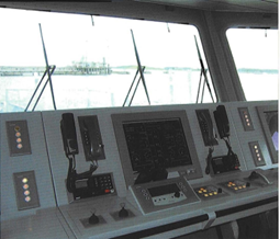
Conning position
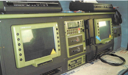
Communication position (GMDSS)
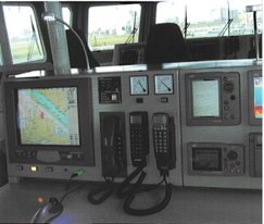
Nautical position
Cables for energy generation and energy conversion:
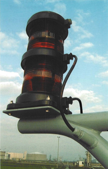
- Navigation lights: outside cables must be screened and run in pipes with open bends, exposed length limited to 20 cm per bend
- Whistle: outside cables run in pipes with open bends
- General alarm system: non-screened cables, no separation
- Main generators: non-screened cables, no separation
- 24 V DC systems: non-screened cables and no separation, with exception supply circuits into the wheelhouse area if not installed inside a steel-clad console. These cables have to be screened, but no separation is necessary
- Starters: both for power and control circuits non-screened cables and no separation
- Lighting: cables to outside lighting must be routed through galvanized steel pipes with open bends. The cable length exposed shall be limited to 20 cm per bend. Non-screened cables and no separation necessary. For wheelhouse area, screened cables and no separation
- Cables between frequency converters and motors must be screened, earthed at both ends, separated from other cables and to be considered as extreme jamming (group 4).
Switchgear and control systems.
- Switchboards/motor control centers: both for power and control circuits non-screened cables and no separation.
- Main lighting switchboard: nonscreened cables and no separation, with the exception of supply circuits into the wheelhouse area, if not installed directly inside a steel-clad console. These cables have to be screened, but no separation.
- Emergency lighting switchboard: non-screened cables and no separation, with exception supply circuits into the wheelhouse area, if not installed inside a steel-clad console. These cables have to be screened, but no separation.
- Lighting distribution panels nonscreened cables and no separation, with the exception of supply circuits into the wheelhouse area, if not installed inside a steel-clad console. These cables have to be screened, but no separation.
Signal processing equipment
- Fire detection systems screened cables, no separation
- The remote control and automation system can be a distributed system with intelligent local units with suitable filtering and limitation circuits. Nonscreened cables for digital input and output is sufficient, but may be executed with screened cables without separation. Analogue input must be executed with screened cables without separation. Data communication between the local units and work stations must be executed with screened cables routed separately from power cables or with coaxial cables
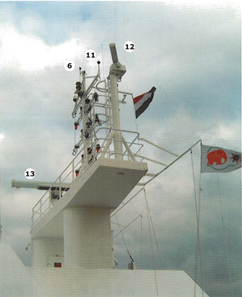
12. X-band (3 cm) radar
13. S-band (10 cm) radar
Non-electric outfit
- Rigging shall be earthed.
Integrated equipment
- Voyage management system: video signals coaxial, network coaxial cables
- Enclosures of equipment in e.g. wheelhouse consoles shall not be taken off or modified without permission of the manufacturer.
Equipment located in hazardous areas
- Cables for intrinsically safe circuits must be screened and clearly- marked, for instance, by colours and separated from other cables
- Cables for power circuits in hazardous areas must be screened for earth fault detection.11. Mast construction and cable routing
The masts of some ships are removable. Therefore, junction boxes are fitted for cables to the equipment in the mast. These junction boxes have to be watertight and have a metal-clad cover, preferably bolted and separately earthed. The mounting plate should be metal and separately earthed. The screen of the cables has to be coupled through isolated terminals.
All cables must be routed inside the mast and/or in steel or aluminium pipes with open bends to avoid interference from Radars and MF/HF aerials.
Cables of group 4 Transceiver cables have to be routed separately from other cables as well as separate from each other. This can be achieved by introducing mounting hatches and fastening strips in two legs of the mast, or in pipes. One pipe to be used for groups 1, 2 and 3 cables and the group 3 cables should be routed separate from 1 and 2 insofar as possible.
The other pipe must be used for the transceiver cables of group 4 and as these cannot be interrupted, there is no need for a junction box. Group 4 cables, however, must also be separated from each other. When this is not possible within the space limitations inside the mast, these cables must be provided with additional screening. This then allows these cables to be routed together. This screening, however, does not fit in the plugs for the equipment. A compromise is thus, to install the additional screen only where the cables run parallel for longer lengths inside the mast and wheelhouse. The screening can then be taken off near the connections at the ends and the original connectors can be used.
12. Cable routing in general
In general, cable routing, trays, deck and bulkhead penetrations must allow for separation as defined before. When separation distances cannot be met, as in the case of a single pipe mast, alternative measures must be taken, such as the installation of an extra screen around a cable. This increases the shielding of the cable and limits the radiation to the environment.
This is applicable to all group 4 cables in this project. Additional screening has to be provided for the longer lengths and screening over the shorter lengths has to be minimal.
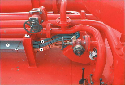
1. Intrinsically safe cables
2. Control cables
3. Cable tray