 +7 (812) 4-673-673
Log
During harbour manoeuvres one wants to know the speed of the vessel in all directions, fore or aft, and the sideways speed of the bow and stern. Log sensors with two axes can give this information (docking system).
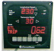
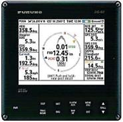
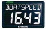 Speed in knots "through the water" at this point in time
The average speed over a certain period of time is useful for passage planning, for example in order to reach a given position by a given time. This might depend on a falling tide, a bridge opening, falling darkness or a berth that is not yet vacant. It could also be useful for dead reckoning.
Knowing the distance run has always been a fundamental piece of information for responsible navigation - and still is. Some logs also display trip distance.
The log can also give information on any tendency for an increase or decrease in speed
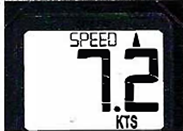
The small vertical arrowhead indicates that the speed is increasing
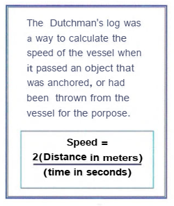
The nautical unit of measurement "knot" is derived from the old way to measure speed using a "chip log". The function of the chip log is to measure how far a vessel travels through the water during a fixed interval of time, usually 30 seconds. A triangular piece of wood (the chip) is thrown overboard attached to the log line. A weight on the bottom edge causes the chipto to take on a vertical orientation in the water. It is thus essential stationary in the water and the motion of the ship causes the log line to be drawn out: more line = higher speed. The log line is marked at regular intervals by short lengths of material with knots on them - hence the expression "knot".
To prevent disturbances from the wake of the vessel and the wind, a lenght of the line was allowed to run out before measurement was begun, and the log was always cast into the sea on the lee side of the vessel.
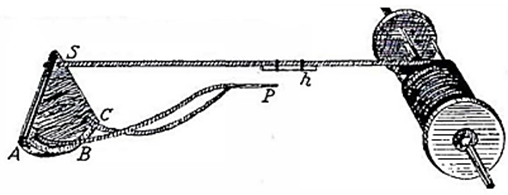
A jerk on the log line caused the wedge P to detach from the sleeve "h". This allowed the chip to take up an orientation parallel to the flow of water so that it could easily be pulled in
2. The acoustic correlation log
The correlation log transmits sound impulses from two sensors that are placed at some distance apart in the fore and aft line of the vessel. After transmitting an impulse the sensors change to receiving mode. The received impulses are used to create a profile of the sea floor. Correlating the two profiles gives a time delay. The speed of the vessel is then calculated with knowledge of the distance separating the sensors.
Because the sensors are directed vertically downwards the signals are fairly insensitive to the ship's movements, temperature and salinity. Two measurement modes are possible: either the speed relative to the water close to the hull (Water Track) or else the speed relative to the sea floor (Bottom Track).
The log can also measure the athwart ship movement at the sensor position. If the sensor is connected to a rate gyro and the distance from the sensor to the bow and stern has been entered then the speed of the transverse movement at bow and stern can be measured using just the one sensor. It can also function as an echo sounder to record depth.
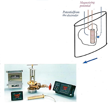
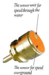 The sensor of the SAL log
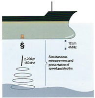 The SAL log measures STW close to the hull using 4 MHz and SOG using 150 kHz to the bottom
Sources of error
At low speeds and shallow depths the time delay may be longer than the length of the signal. Under these circumstances statistical signal treatment methods have to be used, which decreases the accuracy to some extent.
The principle of the electromagnetic log (EM log) is that a potential difference will be induced in a conductor when this is moved in a magnetic field. The sensor of the electromagnetic log contains a coil which creates a magnetic field. On the sensor casing there are two points in contact with the sea water. The water between the contact points acts as the conductor and as the vessel moves forward so a potential difference is created in the water around the sensor.
Electromagnetic logs show Speed Through the Water and have an accuracy of about 0.1 knots. However it is important that the sensor is kept clean and is sited in an area that is free from turbulence.
Sensor are available in a two-axle configuration and these also give athwartship speed. The electromagnetic log has the advantages that it is not affected by depth and salinity variations and it has no moving parts. Also the relationship between the sensor signal and speed is linear, which means that sensitivity is equally good at all speeds.
The Doppler log makes use of the Doppler effect, which is the change in frequency of a signal that is experienced by a receiver whose movement changes relative to the signal transmitter. The Doppler log transmits signals that are reflected from the sea bed back to the receiver. To give Speed Over Ground the depth must be less than a certain maximum depth (200 - 500 meters). In greater depths the log measures signals that are reflected from deep water layers, in which case the speed registered is Speed Through Water.
The single axis Doppler log measures only the longitudinal component of the Speed Over Ground. Doppler logs with two axis also measures its transversal component.
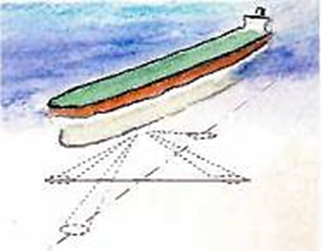
Doppler lags are available in single or quad directional configurations. Four transmitted signals allow the measurement of the transverse speed of the vessel
When Doppler Log information is connected to the network, other navigation options may be displayed
Sources of Error
The first requirement for the correct functioning of the Doppler log is that the sensor is properly mounted. It must be protected from interference from bubbles and the cable connections must be free from electrical interference.
The sensor can be designed to eliminate the effect of variations in salinity and temperature. Different bottom materials give reflections of varying quality. Hard sand gives the best reflection and mud the
poorest. Changes of trim and heel may affect the accuracy. Different manufacturers provide individual solutions to these effects. Single-axis installations may be seriously affected by rolling and pitching. Two-axis systems enable the errors introduced by these behaviours to essentially cancel out each other.
The signal could be attenuated by a poor installation, in the water and on reflection from the bottom. When the system noise becomes as large as the reflected signal, the sensor is unable to measure the frequency of the detected signal.
5. Speed by tachometer (revolutions counter)
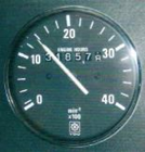
It is possible to get a speed indication from a table of speed measured against revolutions per minute. This does not permit accurate navigation but is good enough for speed control in areas with speed limits and for approximate estimations of DR and ETA.
Speed measured in this way varies according to several factors:
- Draft
- Bottom fouling
- Rolling, which tends to decrease speed
6. Impeller log
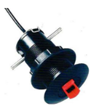
Smaller vessels are often equipped with a log connected to a small paddle wheel as a sensor. These sensors are sensitive to fouling but it is usually possible to retract them for cleaning.
Impeller logs can show:
- Speed through water
- Distance run off
- Trip distance
- Average speed, maximum speed and tendency (increasing or decreasing)
They can be set to show speed in knots, statute miles per hour, and so forth.
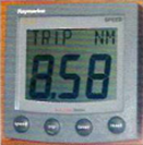
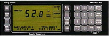
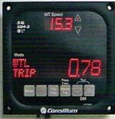
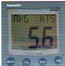 Logs showing: trip distance and average speed
Log sensors for measuring speed through the water, which are mounted at the surface of the ship's bottom, may give an incorrect reading because the water layers closest to the ship's bottom tend to move to some extent with the ship. Logs may also show incorrect values because the zero mark is not correctly positioned. Speed-dependant errors may also be present.
The accuracy of a two-axis Doppler log when measuring to the bottom is 0.2 - 1knot, depending on the manufacturer. When measuring against water the accuracy is generally lower, caused by turbulence at the ships bottom, especially in shallower water.
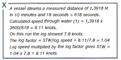
Logs are calibrated by reference to correct speed or correct distance. Correct speed can be calculated from a known distance when steaming at an even speed, or it can be obtained from GPS data provided that there is no current.
|
STW is calculated = (Dx3600)/t in seconds Log correction factor = STW/displayed speed |
The most accurate calibration is made over a measured distance, with the distance to be run marked by transit marks.
To eliminate the effects of any current that may be present the distance is steamed in both directions and the average of the two runs taken. The current effect cancels out.
Doppler and Correlation logs measure against the sea bed providing the depth is not too great, so there is no current effect..
Electronic logs have a calibration setting in their menus.
The log factor is calculated as follows:
.
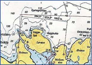 A measured mile in Oslo fjord
To get STW read off the log and multiply the value by the log factor.
For a more complete understanding of the log error it is useful to carry out this procedure at several speeds. Some electronic logs can store up to four log factors for different speeds in their memory.
There are several possible ways to calibrate electronic logs.
- The log is adjusted to show the same SOG as STW read off the navigation system. This presumes that there is no current (simplest).
- Enter a log factor. Some logs can store log factors for different speeds.
- Steaming up and down a measured distance. The distance is entered into he log and the Navigator marks when measurement starts. From this the log can calculate the correction factor.
IMO accuracy demands:
- Errors in the indicated speed, when the ship is operating free from shallow water effect and from the effects cf wind, current and tide, should not exceed 2% of the speed of the ship, or 0.2 knots, whichever is greater.
- Errors in the indicated distance run, when the ship is operating free from shallow water effect and from the effects of wind, current and tide, should not exceed 2% of the distance run by the ship in 1 h or 0.2 nautical miles in each hour, whichever is greater.
- If the accuracy of devices to indicate speed and distance run can be affected by certain conditions (e.g. sea state and its effects, water temperature, salinity, sound velocity in water, depth of water under the keel, heel and trim of ship), details of possible effects should be included in the equipment handbook.
- The performance of the equipment should be such that it will meet the requirements of these standards when the ship is rolling up to ± 10°and pitching up to ± 5°.
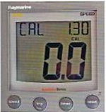 Electronic log in calibration setting. By entering the log factor setting more accurate values will be shown
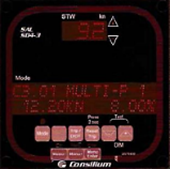 SAL log set up for calibration for several intervals