 +7 (812) 4-673-673
The making of a cable
Cables come in a variety of sizes, materials and types dependent on their application.
Cables are made up of three major components:
- one or more layers insulation
- one or more protective jackets.
The construction of a cable and the materials used are determined by the following factors:
- current-carrying capacity, determining the cross-sectional size of the conductor(s).
- environmental conditions such as temperature, water, chemicals or sunlight exposure.
- mechanical impact, determining the form and composition of the outer cable jacket.
Application which determines, amongst others, the required flexibility of the cable. Cables come in all shapes and sizes for a wide range of applications. From network cables, fibre optic cables, low voltage cables to high voltage cables and everything in between. Larger power cables use so-called sector shaped conductors which makes these thinner than when circle-shaped conductors would be used. Non-conducting filler strands may be added to the cable assembly to maintain its shape.
For installation in ships most cables are specified to be of the low smoke, halogen free type. This is because halogenated materials in cables will release corrosive electronics wherever the smoke travels, and the toxic element can be potentially hazardous to persons. This concern is particularly important in places where many people will be around like in the accommodation of a ship.
Most power cables nowadays are using polymers or polyethylene, including (XLPE) for insulation of the cores which allows the cables to be used with higher core temperatures than the older cable types that use PVC insulation.
Special cables are often custom- made like the cables for connection of a Remote Operated Vehicle (ROV). Those cables are more often hybrid cables that include conductors for power supplies, control signals and fibre optic fibres for data transfer and CCTV signals.
Medium and high volt cables
Cables for use in medium or high voltage installations, above 1000 volts, have extra conductive shields between the conductors and a conductive shield may surround each insulated conductor. This equalizes electrical stress on the cable Insulation. The individual conductor shields of these cables are connected to earth I ground at the ends of the cable. To enhance safety medium and high voltage cables have a distinctive colour from other cables, mostly bright red, and are installed on separate cable supports.
Cable manufacturing
Cable manufacturing involves a number of stages, starting with raw materials such as large quantities of thick copper wires. As an example the following is a brief description of the various stages in the manufacturing process of a larger type power cable with a steel braiding for mechanical protection.
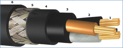
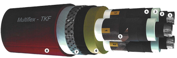
Different layers of power cable:
The image at the bottom of this page shows the various layers of the power cable which will be described with the following components:
1. Stranded copper cores
2. Individual core insulation
3. Filler compound between cores
4. Insu lation material over cores.
5 Steel braiding
6. Insulation material over steel braiding.
The manufacturing process will follow this list, the numbers in brackets correspond to the cable part number in the list.
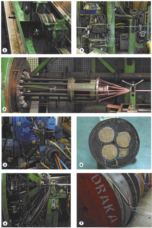
To get a particular size of copper wire for a type of cable the raw copper wires are pulled through drawing dies, set to the correct size, by friction wheels. (Image 1)
The individual cores are twisted into stranded conductors (1). (Image 2)
The individual cores are covered with an insulating material like cross-linked polyethylene (XLPE) with a specific colour to identify the use of the conductor. For power cables this will be phase, neutral or ground when included (2).
The individual isolated conductors are twisted together (Image 3) and a filler compound is added between the wires (3).
An inner insulation layer is applied over the twisted cores and filler compound (4).
A layer of steel wires is spun around the inner isolation layer forming the steel braiding (5) (Image 4).
An insulation layer is applied over the steel braiding (6) (Image 5).
A cross section of a power cable is shown as an example of the structure. (Image 6) This cross section is from a cable without the inner isolating layer but with the filling compound. Each phase is built from 39 sub cores with each about 40 wires, so in this example each phase will have close to 1600 smaller individual copper wires.
When the manufacturing process is completed the cable is ready for the manufacturer's tests and after that ready for delivery (Image 7)
Cable trays and cable fixing
For minimum internal radia of bends for low voltage cables, an average figure of 6 times the overall diame- tre is a reasonable rule of thumb. Above 1000 V, i.e. high voltage cables, the figure lies between 15 times the overall diametre for multi-core cables and 20 times for single-core cables.
Also, the environmental temperature during installation must be taken into account; at temperatures lower than plus 5° centigrade, pulling of cables must be stopped, as the outside screens and core insulation are likely to be damaged.
High voltage cables must be segregated from low voltage cables.
Cables have to be type-tested, or in case no type approval is available, tested by the manufacturer and certified by the classification society. These tests must include:
- high voltage test
- insulation resistance measurement
- for high voltage cables, partial discharge tests.
All tests have to be carried out in accordance with a relevant standard by the manufacturer prior to dispatch.
Fixed cable supports for a single or a small amount of cables are simple steel strips welded to the ship's structure. For larger quantities of cables, ladder type trays are used.
Cable trays come in different sizes and are made of different materials. The simplest are the cable trays made from ordinary steel which are painted before the cables are pulled.
Outside cable trays are hot dipped galvanized or made of stainless steel. When stainless steel is used care must be taken to isolate those cable trays from ordinary steel supports to avoid galvanic corrosion. When weight is an issue, aluminium type cable trays are used. In that case a seawater-proof type must be selected to avoid excessive corrosion.
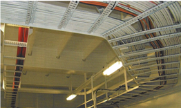
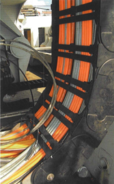
Examples of fixed and flexible cable trays
In any case, all cable tray types other than the ordinary steel types will be more expensive both for material and installation cost. When weight is an issue light weight cable trays made of a glass fibre reinforced composite material can be used. These types of cable trays are identified with FRP or GRP.
Cables are normally fixed with plastic bands, so-called Ту-raps, which should be of UV restinstant material when used outside. Steel cable bands are used when cables are mounted on vertical cable trays or when on the bottom side of overhead horizontal cable trays.
When single core or high voltage cables are involved special consideration should be given to the choice of materials, (non-magnetic, stainless steel)
Maxium distances cable supports
|
External diametre of cable |
Non-armoured cables |
Armoured cables |
|
|
exceeding |
not exceeding |
||
|
mm |
mm |
mm |
mm |
|
- |
8 |
200 |
250 |
|
8 |
13 |
250 |
300 |
|
13 |
20 |
300 |
350 |
|
20 |
30 |
350 |
400 |
|
30 |
- |
400 |
450 |
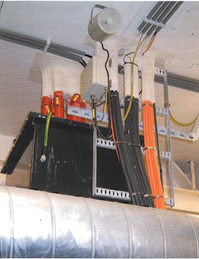
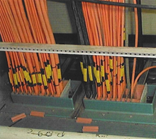
Additional fire protection by application of fire resistant coating (white covers at the top) around cables, passing through a fire-insulated deck
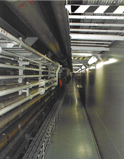
Pipe and cable tunnel in a ship for heavy cargo
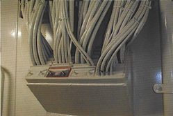
Watertight cable penetration (MCT, Multi cable transit
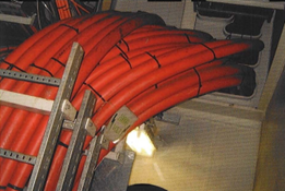
High voltage cables
Minimum bending radia for fixed cables
|
Cable construction |
Overall diametre of cable |
Minimum internal radius of bend (times overall diametre of cable) |
|
|
Insulation |
Outer covering |
||
|
Thermoplastic and elastomeric 600/1000 V and below |
Metal sheathed Armoured and braided |
Any |
60 |
|
Other finishes |
< 25 mm > 25 mm |
AD 6D |
|
|
Mineral |
Hard metal sheathed |
Any |
6D |
|
Thermoplastic and elastomeric above 600/1000 V - single core - multicore |
|
|
|
|
Any |
Any |
20D |
|
|
Any |
Any |
15D |
|
High voltage cables
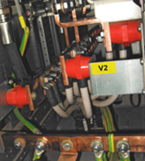
High voltage cables are slightly different, from a construction point of view. Above 3kV HV cables have a radial field construction with an earthing screen between the cores and the outside insulation. A radial distribution of field strength is obtained by making the transfer of field strength radially from the conductor to the insulation and from the insulation to the screens, by means of semiconduc- tive layers and special installation parts. Radial means homogeneous field strength resulting in minimum electrical stresses.
High voltage cable must be tested after installation and on completion of termination.
The special installation parts consist of a shrink-on 3-pole sleeve that connects the cable lug on the core to the core semiconductive layer and the core shield to the semiconductive layer around the core insulation.
2. Semiconductive XLPE with semiconductive tape
3. XLPE core insulation
4. Semiconductive XLPE with semi conductive tape
5. Core shield with copper tape and copper round braiding
6. XLPE inner sheath
7. Galvanized steel wire braiding
8. Outer screen MBZH red.
Radial field cable

Telescopic supported wheelhouse
Multiple glands with rubber sealing blocks
Flexible cables
Marine standard cables are suitable for fixed installation onboard ships and offshore installations. Although provided with stranded conductors, these cables are only suitable for fixed limited movement and at favourable temperatures. A vertically moving deckhouse, in use on inland waterway ships, enabling passing under bridges or for proper lookout in case of a high cargo, requires special flexible conductors. The insulation materials and sheathing materials need to be of a more flexible type, in connection with the expected environmental conditions such as frost.
Additional attention to special cables, such as coaxial cables, is required to achieve the required lifetime.
Cable penetrations
Multiple and single cable penetrations are determined in a similar way. A watertight bulkhead requires a different type of penetration compared with those for a fire bulkhead or -deck. Standard cable penetrations are A-60 fire resistant and are watertight up to a pressure of 50 metres water column. They are readily available in several types, such as cast types, sealed with a suitable compound after completion of the installation.
Multicable transits (MCT's) use a steel frame that is welded or bolted in a deck or bulkhead. The cables pass this steel frame and the space between the cables is filled with accurately selected rubber blocks. When all blocks are fitted a larger pressure block is inserted that is expanded to seal the MCT. This system allows opening of the cable transit and adding more cables at a later date
Многокабельные или однокабельные проходки делаются похожим образом. Водонепроницаемые переборки требуют иного вида проходки, по сравнению с проходкой через противопожарную переборку или палубу. Стандартные кабельные проходки имеют огнезащиту А-60 и водонепроницаемы до давления 50 м водной колонны (5 бар). Легко приобрести разные их типы, включая проходку с заливкой, которая герметизируется подходящим компаундом после завершения прокладки кабелей.
Certification
Design Appraisal Document (or Certificate, depending on the Classification Society) is a statement that the Class has examined drawings or prescriptions of equipment (or an alteration) and that that has been approved for the intended use. In this case it handles electric cables, intended to be used on board ships. It declares that the cables are fabricated in accordance with the Rules for Steel Vessels (ships) and in accordance with the MODU Code, the Rules for Mobile Offshore and Drilling Units.
Also when a conversion to an existing, classed ship or offshore unit has to be carried out, which is subject to Class approval, such a statement has to be issued after examination and approval of the drawings which in such a case have to be submitted for approval.
Subject to, approval are changes to the ships construction or to all equipment which is part of power generation, propulsion, watertight integrity, as far as this is described in the Classification Rules and Regulations or by SOLAS.
SOLAS is in principle a Flagstate matter, but is by many countries delegated to Class.
Often the relevant drawings are provided with comments, which the local surveyor, during approval at the location of the conversion has to check.
These comments are in such case written on the DAD. The local surveyor refers to the particular DAD in his report on completion of the work
Cable connections
A vital part of the electrical installation are the cable connections as these make the real connections between the various parts of the systems.
Cable connections come in all shapes and sizes to suit every possible type of connection like for example:
- Low voltage power cables
- Multicore cables
- Coaxial cables
- Fibre optic cables
- Network cables.
Every type of connection has its own specific requirement and there are large specialist companies, who have developed and produced a whole range of cable connections. One development is the push-in terminal (PIT) for control cables which does away with the screws and saves connection time.
Power connections, both for high and low voltage, are most critical especially when these are for large currents. When these connections are not made with the correct cable lugs for the wire-cross section and crimped with the right tool the connection may be loose.
A loose connection has a higher resistance which generates heat which eventually can lead to a fire. This also applies to the bus bars in switchboards.