+7 (812) 4-673-673
Sources of error of magnetic field sensors
The lines of force of the earth's magnetic field are seldom strictly parallel to the meridians. The angular difference in degrees between the direction of the lines of force and the meridian is called variation. Lines that join points of equal variation are called isogons.
The lines of force of the magnetic field do not describe great circles between the magnetic poles but are disturbed by local conditions. The magnetic field is not static but is slowly changing.
English) can be considered constant within a restricted area but changes across the surface of the earth and with time. There are slow changes, diurnal changes and changes associated with alterations in the magnetic activity in the ionosphere. Added to this, the crust of the earth also contributes magnetic anomalies. This causes local alterations of variation. Information on the magnitude of variation can be found from the compass rose that is found on charts. Variation is said to be Easterly, or "positive", when the magnetic north lies to the east of the meridian and vice versa for Westerly, or "negative" variation.
Chart compass roses also provide information on the annual rate ofchange of variation.
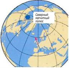
Variation occurs because the magnetic poles do not coincide with the geographical poles. In addition there are also local disturbances. (Map from mapAbility.com)
 Symbol for an area of magnetic disturbance
US/UK World Magnetic Model -- Epoch 2010.0 Main Field Declination (D)
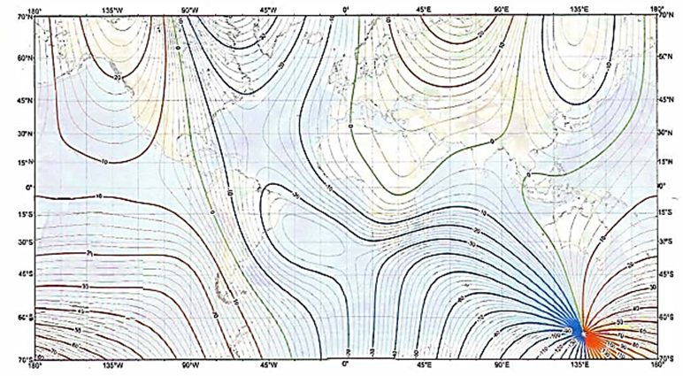
Electronic charts don't have a compass rose with variation information. But the satellite receiver can be programmed with the WMM, World Magnetic Model. When a satellite receiver and an electronic compass are part of a network then the compass course can be automatically corrected for variation. Calculate variation at a given position: NOOA Geomagnetic Data WMM Home.
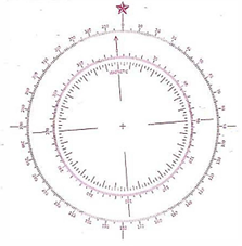
The outer compass rose shows true courses and bearings. The inner ring, whose 0 datum is aligned on the direction of the earth's magnetic field, therefore shows magnetic courses and bearings
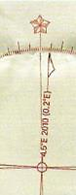
Compass rose from a chart, showing information on the size and annual change of variation. T
he Variation will in this case in 2016 be 4,5° + (6 x 0,2)=5,7ZE
2. Deviation
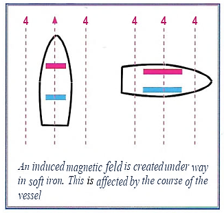
Steel vessels have a permanent fixed magnetic field which develops as the ship is assembled. When under way a further, changeable magnetic field is induced in soft iron depending on the course and latitude of the vessel.
It is conventional to colour-code the magnetic poles with blue and red. The North magnetic pole is the blue one. This convention results in the North-seeking end of the compass magnet being given a red colour.
A permanent magnetism is inducedin the hard iron cfa vesselduring construction,depending on the materials usedandthe orientation within the earth's magnetic field. This fieldremains independent of the course of the vessel
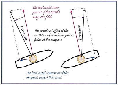
The compass needle is directed by the horizontal components of the forces involved
The angle between the magnetic field of the earth and the magnetic field at the compass is called deviation. Deviation varies depending on the course being steered and the position of the compass on the vessel. Moveable magnetic objects in the vicinity of the compass will change the deviation.
Deviation decreases as the reciprocal of the square root of the distance (1/Va) from a magnetic source. This means that the influence of a magnetic object on a sensor is strongly diminished as the distance
between them increases.
Some types of iron (semi-permanent) have magnetic characteristics that are intermediate between permanent and inducible. This sort of iron becomes magnetised if the vessel holds its course for a substantial period of time, but this doesn't show until the vessel makes its next large course alteration. A lag effect is created that decreases over time and for which it is impossible to compensate.
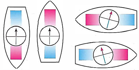
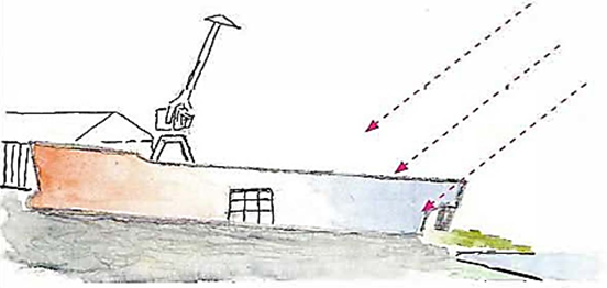
Deviation caused by a permanent magnet is maximum on two courses and zero on two others. When the permanent magnetism of the vessel is as shown in the diagram then the force making the compass needle North-seeking is weakened on a northerly course and strengthened on a southerly course. Vertical soft iron structures affects the compass in the same way as permanent iron, except that it changes polarity on crossing the magnetic equator
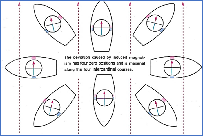
Deviation with horizontal soft iron oriented athwartship.
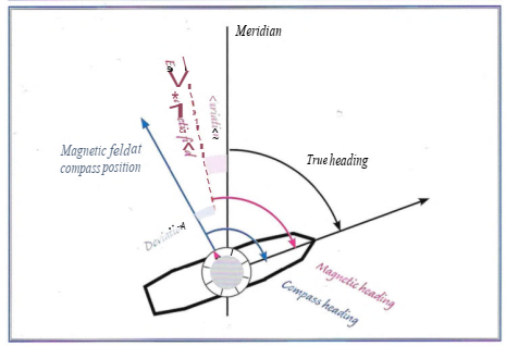
The compass needle will take up its direction in the magnetic field that surrounds it. This direction is the resultant of the strengths arid directions of the magnetic fields of the earth and the vessel. Depending on the reference, courses have different names.
Checking for deviation
There are a number of ways to find the deviation of a magnetic compass. It is standard operating procedure to carry out routine controls of compass deviation while sailing on different courses and from these observations construct a deviation table. This quantifies the residual deviation, the deviation that is uncompensated. The complete elimination of deviation requires the compass to be adjusted.
A reference point is needed both for the adjustment and elimination of deviation. This is provided either by a leading line between two structures, e.g. leading beacons, or by an angle which is read off another compass.
When a true course or bearing from the chart is corrected for variation, the result is called the magnetic heading or magnetic bearing. If the compass on board is compared with that result then the difference gives the deviation (with the correct sign).
|
Magnetic heading - Compass heading = Deviation
|
If the magnetic course is larger than the compass course then deviation is positive, and in the reverse case, negative.
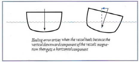
Deviation varies depending on the course, the location of the compass on board, the actual latitude and the degree of heel of the vessel. Different compasses in the same location will have the same deviation.
Deviation should be assessed on at least eight, and preferably more, courses.
Comparison with the gyro compass
Gyro compasses also have errors for which they can usually be compensated. If not then the gyro error has to be taken into account.
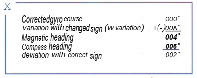
The gyro course is first corrected for variation. Changing the sign gives the magnetic course. If this is then compared to the course shown by the magnetic compass one arrives at the deviation, with correct sign.
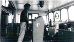 Reading the magnetic compass on the roof of the bridge through a periscope to make a comparison with the gyro compass
Calculating deviation using a transit
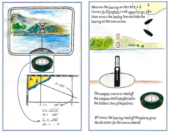
The direction of a transit (leading line) is defined by two points on the surface of the earth. Measure the direction on the chart.
Align the vessel on the transit and steer along it. Read off the Compass course. The difference between the chart value and compass value is caused by variation and deviation. Variation is eliminated by calculating it with the opposite sign. The best transits go through a pair of navigational marks, with the direction given as a bearing on the chart.
Calculating deviation using a bearing
If the vessel has a pelorus then a single leading line is sufficient for deviating all courses.
The true bearing of the leading line is corrected for variation, using the opposite sign. The result is the magnetic bearing. This is compared to the pelorus bearing and the difference is the deviation for that compass course.
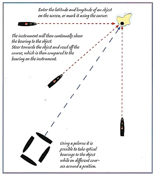
Bearing by satellite receiver
The satellite receiver can be used to obtain a true bearing to an object. Enter the position of the object as a waypoint. This can be done in several ways; by entering latitude and longitude, by marking the object on the electronic chart using the cursor , or by passing close by the object and making a mark in the satellite receiver.
After this the instrument will supply a continuous bearing to the object. It can be set up to show the magnetic bearing, which can then be compared to the compass bearing. The difference is the deviation.
It is important to note that the GPS parameter Course over Ground (COG) cannot be used in this context because COG is obtained by averaging over a certain period of time and is affected by leeway and currents.