 +7 (812) 4-673-673
Harmonic distortion
Harmonic distortion of the main power supply is a phenomenon caused by switching, particularly of high speed power switches as can be found in Variable Frequency Drives. This high speed switching causes harmonics currents which are usually the multiples of the supply fundamental frequency, produced by 'non-linear' loads such as the AC to DC power conversion circuits in the Variable Frequency Drives.
For example, on a 50Hz supply, the 5th harmonic is 250 Hz, 7th harmonic is 350 Hz, etc. These are called 'integer harmonics' - i.e. exact multiples of the supply frequency. The average value of all the harmonics is the Total Harmonic Distortion or THD. With the increased use of large variable frequency drives the danger of the effect of high THD levels has increased too. Classification societies use a value for the THD of 5% or less for use on ships.
The main effects and dangers of high THD levels are:
- aging of the installation due to excessive heat
- malfunctioning and failure of electronic equipment
- overheating and failure of electric motors
- resonance due to interaction of capacitors with harmonics
- overloading and overheating of distribution transformers and neutral conductors
- excessive measurement errors in metreing equipment
- uncontrolled operation of fuses, circuit breakers and other protective equipment
- electromagnetic interference with TV, radio, communication & telephone systems.
By good design and installation practices THD problems can be prevented.
As the biggest source of THD values will be large variable frequency drives selecting the right type in relation to the network can be a big advantage. The rating of the generators supplying the system and their reactance Xd" are a factor with the calculation of the THD.
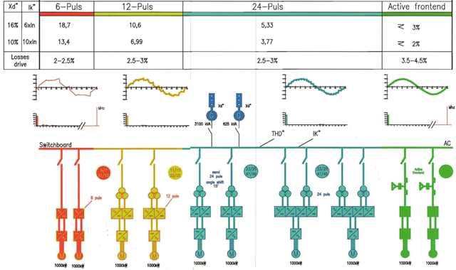
The following basic types of variable frequency drive systems are available which are shown in the diagram on this page:
2. Two double one-way rectifiers, 12-pulse with primary one double stock transformer
3. Two double one-way rectifiers, 12-pulse with primary one double stock transformer with 15 degrees phase shift creating semi 24-pulse system.
4. Four one-way rectifiers, 12-pulse with two primary double stock transformers creating 24-pulse system.
5. Active Front End Converter.
The diagram shows the effect of the different types of variable frequency drives on the THD. The values used to make the calculations are in the diagram
One-way rectifiers (Amber)
The 3-phase AC from the switchboard main bus-bars is rectified by 6 diodes into 6 currents DC which are brought together resulting in a pulsating DC. See diagram. This DC is the sum of the three phases, where the negative part of each sinus is made positive. This forms a DC current with 6 pulses per original cycle, and no possibility of feeding back to the switchboard. This DC is transformed into 3-phase AC again through inverters with adjustable voltage and frequency.
One-way rectifiers (Yellow)
Between the bus-bar and the rectifiers, behind the main switches, transformers of the double stock type are installed. A double stock type transformer has two secondary windings, one in star and one in delta, so producing 6 sinus curves each. The output of one transformer is brought out of phase as much as 30 degrees. The voltage is not necessarily changed. The thus produced 12 currents are rectified similarly to the situation above, and is rectified to a 12-pulse DC. This 12-pulse DC is changed into the desired current in inverters, in voltage and frequency. This output is used in two consumers, running in phase. The distortion on the main bus-bars is considerable reduced.
One-way rectifiers (Blue).
The same as above, but the output of the second transformer is shifted another 15 degrees. The consumers, identical, are using 12 pulses each, but 15 degrees out of phase relative to each other. The distortion on the bus-bar is now 24 pulses, and has less effect again.
One-way rectifiers (Another blue).
Each inverter supplied by two double stock transformers, resulting in 24 pulses to each consumer, a further reduction of the distortion.
Active front-end converter (Green).
This means that the input is not just a rectifier which is controlled by the input voltage, but a controllable device. Controllable devices can stop and pass voltage without the restrictions of a rectifier, so independent of the input voltage. These devices, thyristors, transistors, IGBT's and whatever types are used, can lead power from the switchboard to the consumer and back from the consumer to the switchboard. Active also means that the converter takes power from the switchboard in a controlled way, thus minimising harmonics. Transformers are only required when the voltages differ substantially.
Harmonics created by converters, supplying consumers, are absorbed by the generators energising the switchboard. The impedance of the generators gives an indication of the capability to absorb harmonics. A low impedance will absorb more harmonics than a high impedance, but is also capable to create a higher short-circuit current, requiring more expensive switchgear.