 +7 (812) 4-673-673
Electromagnetic compatibility
The shortest definition of EMC is that this is the capability of an electric system to neither disturb or be disturbed via radiation or transferred through the connection cables. It also includes disturbance by signals in cables not connected to the disturbed unit but signals running through cables parallel to cables of the disturbed unit.
EMC management
Determining if an installation fulfills the EMC requirements is a complicated and time consuming exercise. It starts with listing the sensitive equipment and verifying their acceptance limits, followed by listing the disturbing equipment and testing their disturbance levels. A lot of this work is done by the suppliers under the type-approval schemes.
The publication IEC 60945 defines the susceptibility and disturbing criteria for navigation and nautical equipment. The figures in that publication present the normal environment which is to be expected on the open deck and inside the wheelhouse of a normal ship. Most navigation and nautical equipment has been tested to be able to cope with this environment. This is simple insofar as the environment is under our control.
However, also radio and radar signals from other ships or shore based traffic guidance systems influence the ship's environment.
The maintenance and development of the IEC standards is a joint exercise of industry, equipment suppliers, shipowners, shipbuilders, classification societies and governments and also forms the basis for the rules and regulations of all classification societies.
IEC TC18 standards are published by the International Electro technical Commision, Geneva, Switzerland, as IEC 60092 series and are available at the national standards institutes. Individual references are given in the respective paragraphs.
For detailed information and procedures, reference is made to IEC 60533 Electromagnetic Compatibility for Electric Installations onboard Ships. Navigation and nautical equipment has been tested in accordance with IEC 60945 and therefore, suitable for the outside maritime environment.
EMC environment
Electromagnetic immunity means equipment is capable of operating satisfactorily under the following conditions:
- Cond low frequency interference 10% under AC supply voltage 50 Hz-900 Hz
- 10%-l% under 900 Hz-10 kHz - 10% under DC supply voltage 50 Hz-10 kHz
- Conducted radio frequency interference under supply of 3V rms. 10 kHz-80 MHz
- Radiated interference 10 V/m between 80 MHz-lGHz
- Fast transients (bursts) 2kV differential on AC power ports, IkV common mode on signal and control ports
- Slow transients, power supply variation, power supply failure, and electrostatic discharge (the phenomenon that happens when you touch a system in winter in dry conditions), with a static discharge voltage of more than 6000 Volts are also considered.

Cable and pipe tunnel, with power cables situated below in the tunnel and the control cables, above
Equipment should not transmit conducted or radiated signals that disturb the correct functioning of other equipment.
Normally the conducted emission is not a problem but the radiated emission limit between 156MHz and 165MHz of only 24 dBpV/m is only slightly above the environmental noise level of today. This is a frequency band associated with VHF emergency communication. Equipment used on board ships should not radiate any signal in this frequency.
Also frequencies of processors in programmable logic computers and other electronic control systems have to be checked against the environment and tested if any possibility of interference exists.
Conducted radio frequency interference 3V rms. 10 kHz-80 MHz Radiated interference 10 V/m 80 MHz-lGHz. These figures are for open deck areas and inside the wheelhouse
EMC measures
To limit the exposed systems, the following measures are implemented: Cables outside the steel structure of the ship have to be screened or installed in steel pipes. The most effective means is to limit the quantity of cable exposed to the outside environment by installing those inside the mast or inside a structure, only exposing them to the outside when absolutely necessary.
This also prevents incoming interference.
A cable located outside will act as a receiving aerial and a transmitting aerial inside the ship if not protected. The actual aerials for radio and radar reception have been designed to cope with the environment. They should not become damaged by excessive signals such as lightning or directional radar or track antennas' signals.
The rest of the disturbing signals come from the installation itself. Disturbing signals come from radar, radio and echo-sounder and sonar transmitters. Most suppliers advise how to install their equipment, what type of cable should be used and how it should be routed in relation to other cables and equipment. These instructions are based on the equipment in their tested housing; therefore, no equipment should be dismantled to fit into a console.
Cables must be selected and routed according to the type and strength of signal they transport. Therefore, suppliers of the equipment have to state what signal group their cables belong to.
Single-core cables with a current exceeding 200 Ampere per core must be routed in a three-phase triangular formation to eliminate the magnetic fields around the single cables. These magnetic fields cause disturbance to all visual display units and cause eddy currents to flow in magnetic materials like ordinary steel which as a result may heat up. Therefore, gland plates for singlecore cables must be of a non-mag- netic material, like stainless steel.
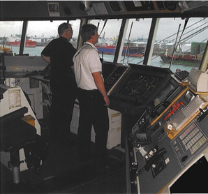
A wheelhouse console is a collection of all type and make of equipment.
Most of those are tested for EMC. This equipment shall be installed in the original housing as it was tested to be sure the required compatibility is maintained.
Also earthing and type of cables shall be as used during the tests
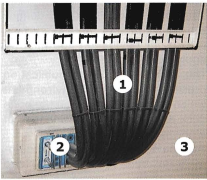
1. Single core cables
2. Multi Cable Transit (MCT)
3. Bulkhead
4. Dec
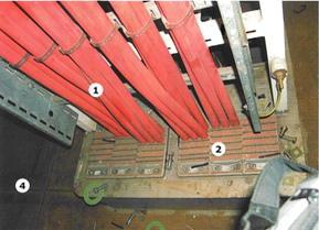
In this bulkhead penetration the sum of the current surrounded by the magnetic material is about zero