 +7 (812) 4-673-673
FMEA (Failure Mode and Effect Analysis)
Introduction to Failure Mode and Effect Analysis (FMEA), Failure Mode and Effect Analysis
Both notations DP (AA) and DP (AAA) have to be verified by a FMEA. This is a method used to determine the consequences of a single failure in the propulsion system and the propulsion control system.
For a diesel electric propelled vessel it begins with the fuel tanks and fuel system, identifying single failures on an empty tank, a failing separator and a failing booster pump and lists the consequences for the propulsion system.
As long as only one propulsor gets involved there is no cause for alarm. As soon as more than one propulsor gets damaged by a single failure upstream of the propulsors, it should be identified so that possible solutions can be determined.
The fully redundant system does not only take into account the equipment located in a space, but also the cable routes to and from the redundant equipment.
An example of non-redundant cable routing is: A power cable for thruster 1 and a control cable of thruster 2, (which is intended to be the back-up of thruster 1), both located at the same cable tray, would not be redundant in case of fire in this space.
Also, if a thruster requires more power sources, for instance lOkV for the main motor, 440 volt for the hydraulic pumps and the lubricating oil pump, 220 volt for the main control system and 24V DC for the emergency control system, it may be far more redundant to obtain all the AC voltages from a single source and obtain the emergency controls from a common DC system.
1. Example of cable laying and ship repair
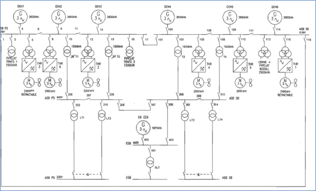
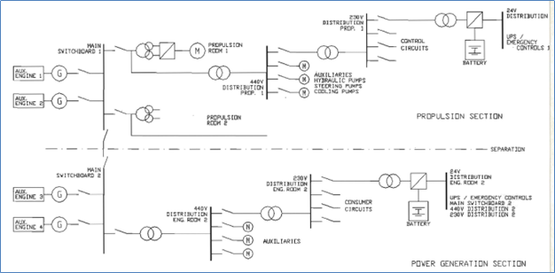
A visual example provides more information than pages of text. At first, a simplified one-line diagram, with, at the top, the power distribution to the propulsors and their auxiliaries. The other 3 propulsors have a similar arrangement: one more from switchboard 1 and the two others from switchboard 2.
The engine rooms are self-supporting, so there is no common failure that can affect two engine rooms, however, there are common systems for two generator sets such as fuel, seawater and freshwater. This allows fewer generators to operate all thrusters during favorable weather conditions in order to save fuel.
An alternative would be diesel direct drive for each thruster in each thruster room with no common systems. At lower loads, this is not effective with regard to fuel, but a lot of equipment is not required in such a configuration (genera tors for propulsion, no HV switch boards, no transformers, converters and electric motors). Instead, there are always four engines running, and because of their limited speed range, variable pitch thrusters are required.
Organizing these systems is an operational choice.
More equipment does not always mean more redundancy.
Direct drives are more efficient than diesel electric systems. The lower part of the above diagram shows half of the distribution system to the generator room auxiliaries. Here, a common distribution system per generator engine room with one transformer from the high voltage switchboard, one 440V switchboard, and another single transformer 440/230V to another single 230V switchboard and a single 24V DC battery-fed UPS system for emergency controls.
This 24V DC could also control the HV circuit breakers which usually lock mechanically in their open or closed position and require power to be operated or opened.
This power is always from a UPS type of power supply to guarantee opening of the circuit breakers during short-circuit or black-out conditions.
The intention is that with a serious problem in one of the engine rooms, such as fire or flooding, the other operating engine room, with its switchboards HV and LV and 230V as well as 24V DC, is still capable of operating its engines, generators, auxiliaries, switchboards.
With the distribution lay-out to the thrusters, a single failure cannot affect more than one of the propulsors. The locations and routing of the cables must be such that a fire does not influence more than one propulsor. The control cables for propulsors supplied from one switchboard can be routed together because a failure of this switchboard would stop these propulsors too.
A similar analysis has to be conducted on the other systems which are required to run the generators and propulsors. Thus, fuel tank arrangement, filling system, separators, etc. must not depend on any item in the other engine room. Ventilation arrangement, location of fans, control gear and power supplies must be independent from the other engine room.
Cooling-water systems, both sea - water and freshwater, in one engine room must be independent from the other engine room.
Also cooling water for one thruster must be independent from all other thrusters.
Hydraulics for a propulsor have to be independent of all other propulsors, thus, no common tanks.
The propulsion controls should be from the associated 24V DC source for each propulsor.
Within the dynamic positioning system, the control circuits must also be divided over different circuit boards in such a way that a single failure will not jeopardize the function of more than one thruster.
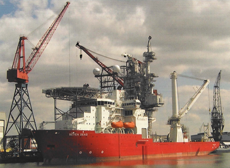
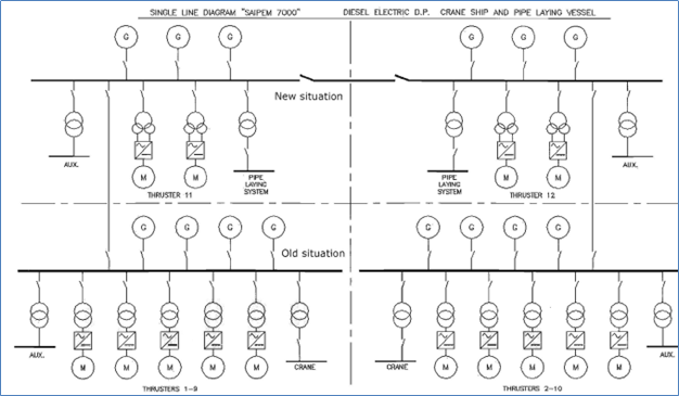
2. Example upgrading crane and pipe laying vessel
The upgrading of a large crane vessel involved two engine rooms, switchboard rooms and thruster rooms and four new thrusters. This resulted in class 3 conditions rising from 50% to 75 % of the totally installed and increased generator capacity.
For a (AAA) certified system with a main and back-up computer control system located in a fire insulated (A-60) space, the control cable routing from the normal computer and the back-up computer must be separated over the full length. The change over from main to backup controls must be physically located as close to the propulsor as possible
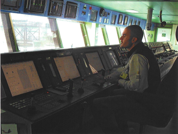
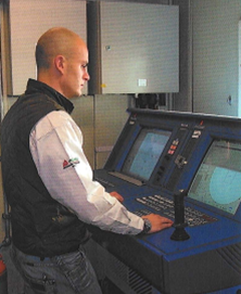
Main DP-console with manual thruster control console in background. Secondary DP console
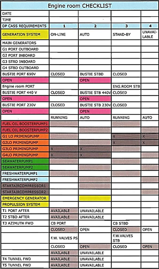
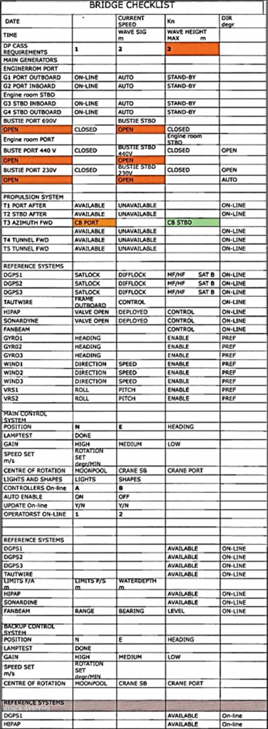
3. Engine room and bridge checklist
To go into DP is a careful exercise and requires planned action and tests from both the bridge and engine room crew. The procedures to change to and from DP-mode are as rigid as for the preparation of an airplane before take-off using check lists.
An example of an engine room checklist
In this example, the Azimuth thruster T3 also requires fresh cooling water from the engine room which has been selected for electric power. These valves are manually operated and must be in the correct position. The checklist must be completed by the engine room crew and submitted to the bridge. The bridge crew checks their part of the system and completed their checklist.
When all settings and tests are correct, the vessel can go in DP-mode.
HiPAP – underwater sonar positioning and navigation system
SONARDYNE (Ranger 2) – family of underwater sonar positioning systems