ECDIS Security Settings
But what if the ECDIS settings are not sufficient or incorrect? Incorrect settings pose a great threat to safe navigation.
Security Settings
Safety settings set the safety parameters in accordance with the static and dynamic characteristics of the vessel. These are ECDIS settings changes that come from traditional paper cards.
For example, is it possible to say that the blue part in this diagram is shallow water?
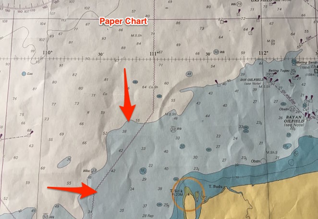
This is so and not so. For a small vessel with less draft, this is not shallow water. For a large container ship with deep traction - maybe.
So, the colors on the paper map may not display the shallow water for all ships. But in ECDIS they can be installed by the user in accordance with their project and other parameters.
There are 4 security settings
- Safety loop setting
- Shallow Water Settings
- Depth Setting
- Setting the contour of safe depths.
To enter a value for these settings in JRC ECDIS, go to: chart -> settings and then select “S-57 / C-Map / ARCS.
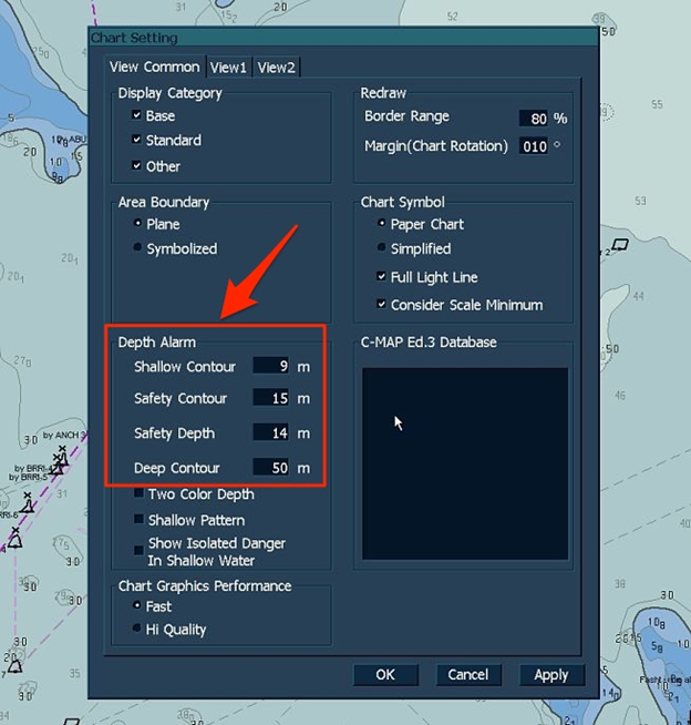
Fine tuning
A path is a line separating a region of minimal depth. For example, a 10-meter circuit will be a line dividing the water below and above the 10-meter depth.
The contours are 5, 10, 15, 20, 30, and so on.
It is necessary to use the value of the contour, shallow water to tell ECDIS what the shallow water value is for our vessel. This is the depth value below which the ship is stranded.
The shallow water contour value should be equal to or greater than the draft.
Let's say the draft of the vessel is 9 meters, and we enter the value of the shallow water contour of 9 meters. ECDIS will display a 10-meter contour line as a shallow water contour. If a 10-meter circuit is not available, the next circuit will be accepted as a shallow water circuit for the vessel.
This contour allows the navigator to know that between the depth of 0 meters and the shallow water contour the region is not navigable at all.
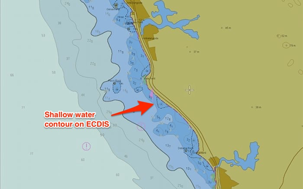
Safety loop setting
A safety circuit is a contour line over which we can navigate without worrying about the depth of the water.
What depth of water is needed to sail a vessel without any problems? Of course, this is depth that is in line with UKC policy.
Let's look at this again with an example. The draft is 9 meters and the maximum squat is 1.1 meters at maximum speed. The company requires the ship to have UKC 10% of draft.
Using the UKC calculation method, we can conclude that this vessel will need 11 meters of depth for navigation.
This is the simplest case. In fact, you need to follow your company's UKC payroll sheets in order to achieve the depth necessary to comply with UKC policies. This may depend on various factors, such as the state of the sea, increased traction due to rolling, density of sea water and high tide.
But the idea is to know the minimum water depth at which you will comply with UKC company policy.
This water depth becomes the setting of the safety loop. Thus, if we enter 11 meters as the setting for the safety loop, it will show the 15 meter loop as the safety loop.
Some companies may provide simpler security setup instructions in the navigation guide. One form of this instruction may be based on ship draft.
When a safety loop value is entered in ECDIS, it gives the depth of the safety loop line that exceeds UKC requirements.
Safe Depth Setting
Safe Depth is the depth of the water through which you can safely navigate.
In ECDIS we need to enter this minimum depth. This is the same as what we calculated as a simple example in setting up a safety loop, and must also follow the UKC design form of the company, which can take into account a number of factors to calculate the required safety depth.
But the question is, why do we need safe depth settings when we can move in waters above the safety loops? This is due to two simple reasons:
1) Depth above the safety loop may not always be navigable
This is the case for shallow depths at one point in navigable waters. Although we can move in the area above the safety loop, this isolated depth is dangerous. Depth of security underlines this danger.
2) Depths below the safety loop may not always be non-navigable
We can understand this if we return to the value of the safety loop that we entered, namely 11 meters, and when we select this value, ECDIS will accept the next available loop. It will be a 15 meter circuit.
Now depths from 11 to 15 meters are available for us, but they will be displayed below the safety loop. Thus, in the area between the shallow water contour and the safe depth contour, ECDIS will show the depth that we can navigate.
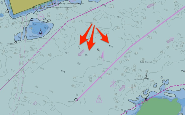
Let's say we set a safe depth of 16 meters. On ECDIS, all depths below 16 meters will be shown more clearly (black compared to other gray colors).
Depth contour
This is a relative term, and the user can establish what, in his opinion, can be deep water for him. For some it is 50 meters, and for others - 30 or 100 meters.
But there are several ways that you can use the deep-sea loop setup.
For example, you can set a deep-sea contour to show the maximum depths at which a ship can anchor. Thus, if your ship can anchor a maximum depth of 105 meters, you can set the deep-sea contour to 100 meters.
Or, if you intend to replace ballast water, you can set a deep-water circuit to 200 meters. Thus, it is easy to determine only by color on the ECDIS that you are at a depth where ballast exchange can be performed.
Setting the deep-sea contour can be used in many ways, and navigators can apply it the way they want.
Delineating Security Settings in ECDIS
What will the ECDIS screen look like with all these settings? For example, a ship has a draft of 9 meters and a ship depth of 14 meters to comply with UKC policy.
So, we have the following settings:
- Shallow water contour - 9 meters
- Safe Depth - 14 meters
- Safety loop -15 meters
- The contour of the depths is 50 meters.
If you enter all these numbers in ECDIS, then these settings will be displayed on the screen:
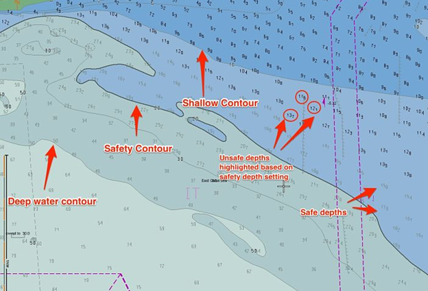
It can be seen here that for the safety loop ECDIS took a 20 meter loop because the 15 meter loop is not available.
ECDIS has another option for using two colors to display these areas. When this option is selected, the following will happen.
- Safety loop and deep loop merge.
- The shallow water circuit and the safety circuit merge.
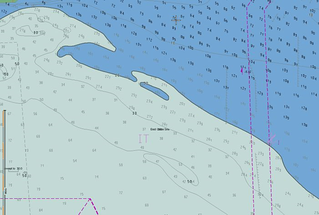
It can be said that cyan and blue merge and become cyan. In the same way, gray and white colors merge and become white.
So there will be only two colors. One to show shallow water, and the other to show navigable water.
Even on a two-color display, we cannot focus on shallow water. This is because it shows the outline, not the depth.
In our example, the dividing line is the contour of 15 meters. The area below this path will be displayed in shallow water (blue). But since the safe depth is 11 meters (which will be below the contour of 15 meters), we can focus on shallow water if the depth exceeds 14 meters.
Hazard Detection Settings
Entering the security settings will alert us when the ship enters shallow waters. But when he gives the alarm, by then it might be too late.
Hazard detection settings can help prevent it. We only need to identify the area in which we need ECDIS to warn us.
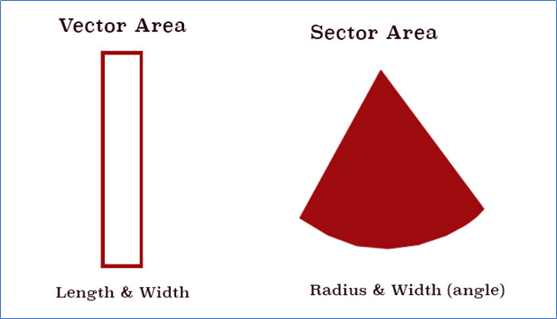
We can define an area in two ways
- Vector area- Sector area.
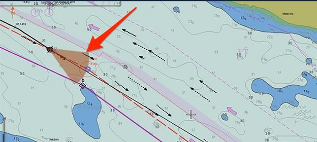
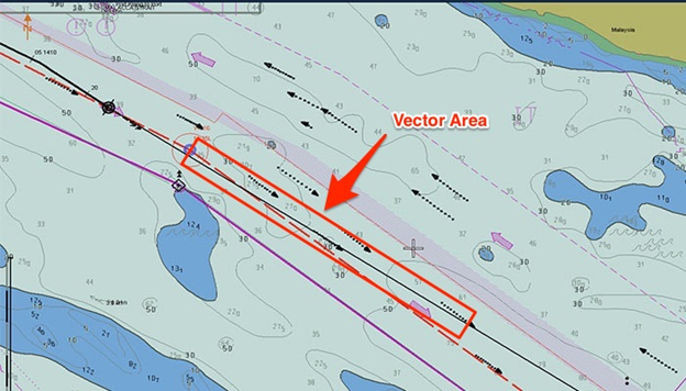
The vector region defines the region by length and width. The area of a sector determines the area in radius and width (angle).
Let's define this area on JRC ECDIS. In JRC ECDIS, go to Menu, Settings and then select Alarm Settings.
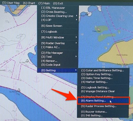
The alarm settings panel opens.
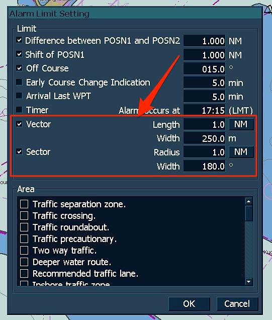
In the Vector and Sector section, you can set the area where you want ECDIS to look to the future. Once these areas are defined, you can enable them by going to “Ownership / Tracking” and selecting “Settings”.
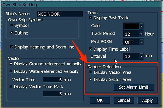
Then you can select “Vector Area” or “Sector Area”. You can even go to the alarm settings page by clicking “Set Alarm Limit” in the “Hazard Detection” section.
When you decide to display the "Vector Area", it will look like this, and ECDIS will work in case of an alarm if it detects any danger in this area.
Alarm settings
But all the security settings in question are useless unless the alarm volume is turned on. If the buzzer volume is muted, ECDIS will not be able to warn the navigator.
However, there are times when we need to turn off the buzzer. For example, in an area with a high traffic density, when we constantly monitor the movement. In this case, frequent alarms will be less important.
Navigators should use their professional competence to decide when they need to turn on the buzzer.
On the JRC ECDIS, to turn on the sound volume, go to “Main”, “Setting”, and then select “Volume Buzzer Volume”.
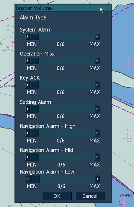
A panel will open from which you can increase or decrease the volume of various types of alerts.
Conclusion
Using the on-board ECDIS makes navigation safer. Of course, there have been many incidents due to the user interpreting the ECDIS display, but training and practice help to bridge many gaps. Knowing what these security settings mean in ECDIS can help in their proper use, which will definitely be a step forward.
 +7 (812) 4-673-673