ENG
Replacing magnetrons in a Sperry Marine radar
Replacing magnetrons in a Sperry Marine radar
23.06.2020
Original Magnetrons for VisionMaster FT
Magnetron current adjustment.
(Only a qualified engineer can carry out such settings in radar stations)
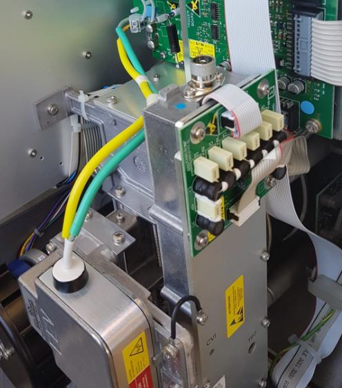
1.2 Install the replaceable magnetron on the surface of the magnetron radiator using 4 removed screws and washers with one coil spring, previously removed. Make sure that the ground cable is connected under one of the screws, as shown in Figure 2.
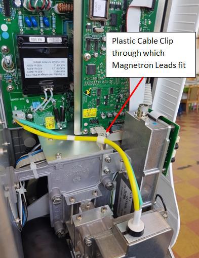
1.3 Pass the magnetron cable through the plastic “P” clip, shown in fig. 1.
1.4 Connect the yellow and green cable to the terminal block on the EHT board. The yellow cable is connected to terminal “Y”, and the green cable is connected to terminal “G”, as indicated on the printed circuit board. Tighten the terminal screws completely.


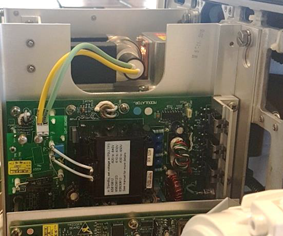
2.2 Install the replaceable magnetron on the surface of the magnetron radiator using the 6 screws and spring washers previously removed, shown in fig. 4.
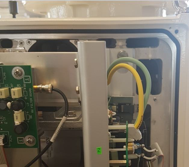
2.3. The magnetron cables are passed through a slot in the side of the transceiver, as shown in Fig. 3.
2.4 Connect the yellow and green cable to the terminal block on the EHT board. The yellow cable is connected to terminal “Y”, and the green cable is connected to terminal “G”, as indicated on the printed circuit board. Tighten the terminal screws completely, see Fig. 4.


It is important to remember that repairs and maintenance of the radar station should only be carried out by qualified specialists in order to avoid further damage.
In order to order repair or maintenance of a ship’s radar, contact the manager by mail sales@cirspb.ru or the service department service@cirspb.ru
Or by phone: in St. Petersburg +7 (812) 4-673-673
and in Petrozavodsk +7 (8142) 57-80-30 and +7 (8142) 57-00-03.
Original Magnetrons for VisionMaster FT
| Part No. | Description |
| T91003582 | X Band Magnetron 10Kw (MG5473) |
| T91003496 | X Band Magnetron 25Kw (MG5424) |
| T910/2666-4 | S Band Magnetron 30Kw (MG5223) |
Magnetron current adjustment.
(Only a qualified engineer can carry out such settings in radar stations)
- X band 10 kW, from 4.5 to 7.0 A (modulator voltage from -610 to -630)
- X band 25 kW, 6.0 to 8.0 A (modulator voltage from -620 to -640)
- S band 30 kW, from 7.0 to 9.0 A (modulator voltage from -630 to -650)
1. Replacing the X-band magnetron:
1.1 The length of the magnetron wire should not exceed 257 mm, the ends of the wires should be stripped 5-6 mm and covered with tin.1.2 Install the replaceable magnetron on the surface of the magnetron radiator using 4 removed screws and washers with one coil spring, previously removed. Make sure that the ground cable is connected under one of the screws, as shown in Figure 2.
1.3 Pass the magnetron cable through the plastic “P” clip, shown in fig. 1.
1.4 Connect the yellow and green cable to the terminal block on the EHT board. The yellow cable is connected to terminal “Y”, and the green cable is connected to terminal “G”, as indicated on the printed circuit board. Tighten the terminal screws completely.


| Picture 1 | Figure 2 |
2. Replacing the S-band magnetron
2.1 The length of the magnetron wire should not exceed 162 mm, the ends of the wires should be stripped 5-6 mm and covered with tin. T910 / 2666-4 has been modified by NGSM.2.2 Install the replaceable magnetron on the surface of the magnetron radiator using the 6 screws and spring washers previously removed, shown in fig. 4.
2.3. The magnetron cables are passed through a slot in the side of the transceiver, as shown in Fig. 3.
2.4 Connect the yellow and green cable to the terminal block on the EHT board. The yellow cable is connected to terminal “Y”, and the green cable is connected to terminal “G”, as indicated on the printed circuit board. Tighten the terminal screws completely, see Fig. 4.


| Figure 3 | Figure 4 |
It is important to remember that repairs and maintenance of the radar station should only be carried out by qualified specialists in order to avoid further damage.
In order to order repair or maintenance of a ship’s radar, contact the manager by mail sales@cirspb.ru or the service department service@cirspb.ru
Or by phone: in St. Petersburg +7 (812) 4-673-673
and in Petrozavodsk +7 (8142) 57-80-30 and +7 (8142) 57-00-03.
 +7 (812) 4-673-673