Справочник для клиентов

Minimum composition of radio equipment

Determined by the sea areas of navigation of the vessel: A1; A1 and A2; A1, A2 and A3; A1, A2, A 3 and A4.


No.

Radio equipment1

Quantity for ships, sea areas

1

2

A1

A1 and A2

A1, A2 and A3

A1,A2,A3

and A4

3

4

5

6

VHF radio installation2: DSC encoder

DSC surveillance receiver

radiotelephone station3

1

1

1

1

1

1

1

1

1

1

1

1

1

MF radio installation2.4: DSC encoder

DSC surveillance receiver

radiotelephone station

-

1

1

-

2

-

1

1

-

-

15

1

-

MF/HF radio installation2: DSC encoder

DSC surveillance receiver

telephony radio receiver and UBDP

radio transmitter for telephony, DSC and UBDP

letter-printing equipment for increasing fidelity

printing terminal

-

-

16

1

-

-

16

1

-

-

16.7

17

3

-

-

16,7

17

-

-

16

1

-

-

16

1

4

INMARSAT ship earth station

-

-

14

-

5

Security Alarm System

18

18

18

18

6

NAVTEX service receiver

19

19

19

19

7

RGV receiver

110,11

110,11

110,11

110,11

8

HF letterpress receiver

telegraphy for receiving IBM

112

112

112

112

9

Satellite EPIRB of the COSPAS-system

SARSAT13

214

214

214

2

10

VHF EPIRB

115

-

-

-


No.

Radio equipment

Quantity for ships, sea

districts

A1

A1 and A2

A1, A2 and A3

A1, A2, A3

and A4

eleven

A device for indicating the location of a ship for search and rescue purposes: ship radar transponder (ship radar transponder) or ship automatic identification system transmitter (AIS transmitter

ship's)

116

116

116

116

12

VHF two-way radiotelephone communication equipment with aircraft17

118

118

118

118

13

Command broadcast device20

119

119

119

119

14

Device for indicating the location of a life-saving craft for search and rescue purposes: radar transponder of the life-saving craft (SAR of the life-saving craft)

or automatic identification transmitter

life-saving appliance systems (AIS transmitter

life-saving equipment)

-21

-21

-21

-21

15

VHF two-way radiotelephone equipment

-21

-21

-21

-21


Notes:

1   - Every ship, in addition to the radio equipment in the table above, shall be provided with a second independent means of giving a distress alert.

To do this, you can use any tool from the table below.

A1

A1, A2

A1, A2, A3

A1, A2, A3, A4

Second VHF with DSC

+

MF with DSC

+

HF with DSC

+

+

+

SZS

+

+

+

COSPAS-SARSAT EPIRB

+

+

+

+

2   - A combined radio installation or in the form of separate devices is allowed.

3   - Continuous hearing monitoring on channel 16 is not limited by the date of its termination.

4   - Not required if you have a MF/HF radio installation.

5   - If the radiotelephone station does not provide transmission and reception in the range 1605 - 4000 kHz, a separate radio installation or MF/HF radio installation, or INMARSAT is provided.

6   - Not required if there is an INMARSAT ship earth station.

7   - If MF/HF does not provide transmission and reception in the range of 1605 - 4000 kHz and 4000 - 27500 kHz, then a separate radio installation is provided.

8   - Required for ships on international voyages: all passenger ships, including high-speed ships, and for cargo ships, including high-speed ships, of 500 gross tonnage or more.

9   - The installation of a receiver is mandatory if the vessel is sailing in any area where international NAVTEX service is provided.

10    - Accepted as part of an SES of a recognized mobile satellite service.

11    - The installation of a receiver is mandatory if the vessel is sailing in sea areas A1, A2 or A3, where international NAVTEX service is not provided.

12    - It is allowed to install this receiver instead of the RGV receiver on ships making voyages exclusively in an area where the transmission of information on maritime safety is ensured using KB direct-printing telegraphy.

13    - One of them must be free-floating.

14    - One EPIRB may be installed (see 3.6.2 of the rules) if the position from which the ship is usually controlled provides distress alerting by at least two separate and independent means using different methods. Communication types that correspond to the vessel's navigation area.

15    - On ships making voyages exclusively in sea areas A1, in agreement with the Register, it is allowed to install a VHF EPIRB instead of the EPIRB of the COSPAS-SARSAT system.

16    - As a device for indicating the location of a vessel for search and rescue purposes, a shipboard PLO operating in the 9 GHz band or a shipboard AIS transmitter operating on international frequencies can be used.

17    - Required for passenger ships.

18    - It is recommended to install two sets, one of which must be wearable.

19    - Cargo ships are exempt from installing a command broadcast device.

20    - It is recommended to install a command broadcast device on cargo ships.

21    - The conditions for supplying ships with radio equipment for life-saving appliances are set out in Part II “Life-saving appliances”.


Optional equipment

In addition, it is recommended to equip ships with:

• security surveillance system –  required in accordance with the transport security regulations

• equipment for receiving fax messages

On each river-sea vessel of inland waterways the following is additionally installed:

• main VHF radio station of decimeter waves

• operational VHF radio station of decimeter waves

• 2 portable VHF radio stations of decimeter waves

• command broadcast device.

On every fishing vessel, cargo vessel with a capacity of less than 300, non-self-propelled vessel intended for towing or for long periods

anchored and with people on board when sailing in area A1, the following equipment is installed:

• VHF radio installation;

• EPIRB of the COSPAS-SARSAT system;

• device for indicating the location of the vessel and life-saving appliance

• VHF equipment

In addition to the above, the following radio equipment must be installed:

—   for ships intended for navigation in sea areas A1 and A2:

• MF radio installation;

• NAVTEX service receiver or RGV receiver, when operating in areas where international NAVTEX service is not provided;

—   for ships intended for navigation in sea areas A1, A2 and A3, as well as in sea areas A1, A2, A3 and A4:

• MF radio installation;

• INMARSAT ship earth station and RGV receiver, or MF/HF radio installation and receiver for receiving maritime safety information;

• Receiver of the NAVTEX service, with the exception of ships constantly operating outside the coverage area of this service.


On every vessel intended to sail within

the internal roadstead of the port water area is established:

• VHF radio installation;

•   a device for indicating the location of the ship and life-saving craft for search and rescue purposes (radar transponder or automatic identification system transmitter);

• VHF two-way radiotelephone communication equipment (1 set).

• COSPAS-SARSAT EPIRB or VHF EPIRB, if area A1 (for external raid)

For oil tankers, oil gathering vessels, gas carriers and chemical tankers:

• The power of the transmitters at the carrier frequency should not exceed 500 W in the antenna (peak 1000 W)

• Wearable radio equipment must be intrinsically safe (with the exception of radio equipment of life-saving equipment)


Additional requirements for duplication of radio equipment

No.

Navigation equipment

Quantity for ships of gross tonnage


Explanations

<150

≥1501

≥3001

≥500

≥3000

≥10

thousand

≥50

thousand

1

Magnetic compass Main 2

1

1

1

1

1

1

1

The compass kit must include a direction-finding device that provides bearings along a 360° arc of the horizon and is independent of any source

electrical energy

2

Magnetic spare compass

-

1

1

1

1

1

1

Should be interchangeable with the main magnetic compass. Not required if complete duplication of the main magnetic

compass

3

Receiver indicator of radio navigation system/systems 3

1

1

1

1

1

1

1

The current coordinates of the vessel's location should be determined automatically

4

Radar

station 4 with means:

-

-

1

1

2

2

2

One radar station must operate in the 9 GHz range (wavelength - 3 cm)

.1 electronic gasket (EPS)

-

-

1

-

-

-

-

.2 auto escort (SAS)

-

-

-

1

2

1

1

.3 automatic radar plotting (ARPA)

-

-

-

-

-

1

1

5

Simplified flight data recorder

(U-RDR)

-

-

-

-

15 _

15 _

15 _

Not required on ships not engaged in international voyages

6

Remote device

transmission rate 7

-

-

16 _

-

-

-

-

-

7

Gyroscopic compass 8

-

-

-

1

1

1

1

The gyroscopic compass kit must include a repeater (repeaters) that ensures taking

bearings along a 360° horizon arc

8

Echo sounder 10

-

-

1

1

1

1

1

-

9

Lag 10

-

-

1

1

1

1

1

Must provide measurement of speed and distance traveled

relative to water

10

Lag absolute 10

-

-

-

-

-

-

1

Must provide measurement of speed and distance traveled relative to the ground in longitudinal and transverse

directions

eleven

Universal automatic identification system equipment

(AIS) 1

-

-

1 11

1

1

1

1

-

12

Course or trajectory control system

vessel

-

-

-

-

-

1

1

-

13

Speed ​​meter

turning

-

-

-

-

-

-

1

-

14

External reception system

sound signals

1

1

1

1

1

1

1

Required on enclosed vessels

bridge and ships with the OMVO sign

15

Registrar

flight data (VDR) 12

-

-

-

-

1

1

1

Not required on ships, not

on international flights

16

Electronic cartographic navigation and information system

i system (ECDIS) 13

-

-

-

1

1

1

1

Duplication must be ensured

17

Equipment for a long-range vessel identification and tracking system

(OSDR systems) 14

-

-

1

1

1

1

1

Not required on ships not engaged in international voyages.

Пассажирские суда, совершающие международные рейсы, должны быть оснащены данным оборудованием независимо от размера

18

Система контроля дееспособности вахтенного

помощника капитана (КДВП)

-

1

1

1

1

1

1

Суда должны быть оснащены системой КДВП в сроки, определенные в 1.1.7 правил

19

Индикаторы:

.1 углового положения пера руля

.2 частоты вращения, усилия и направления упора гребного винта

.3 шага и режима работы винта (винтов) регулируемого шага15

.4 усилия и направления упора подруливающего устройства

(устройств)16

-


-


-


-


-


-


-


-


-


-


-


-


1


1


1


1


1


1


1


1


1


1


1


1


1


1


1


1


Показания индикаторов должны быть видны с места, откуда обычно осуществляется управление судном

20

Радиолокационный отражатель17

118

-

-

-

-

-

-

-

21

Лот простой

(ручной), комплект

1

1

1

1

1

1

1

-

22

Секстан навигационный

-

-

1

1

1

1

2

-

23

Хронометр

-

-

1

1

1

1

1

На пассажирских судах и судах специального назначения валовой вместимостью более 300

требуются два хронометра

24

Секундомер

-

1

1

2

3

3

3

-

25

Глобус звездный или равнозначный

прибор

-

-

-

1

1

1

1

В ограниченных районах плавания R2, R2-RSN, R2- RSN(4,5), R3, R3-RSN - не

требуется

26

Бинокль призменный

1

1

1

2

3

4

4

-

27

Анемометр

-

-

1

2

2

2

2

Не требуется на судах

ограниченного района плавания R3

28

Барометр-анероид

-

1

2

2

2

2

2

-

29

Кренометр

1

1

1

2

2

2

2

На судах, на которых требуется установка РДР и построенных после 01.01.2019, как минимум

один кренометр должен быть электронным

1 - Включая пассажирские суда, независимо от размеров.

2 - Должна обеспечиваться дистанционная передача показаний основного магнитного компаса к основному посту управления рулем.

3 - Используемая система радионавигации (глобальная навигационная спутниковая система или наземная радионавигационная система) должна быть доступна для использования в любое время в течение предполагаемого рейса.

4 - Если требуется установка двух радиолокационных станций, они должны работать независимо друг от друга.

5 - Не требуется на судах, построенных 1 июля 2002 года или после этой даты.

6 - Должна обеспечиваться передача информации о курсе в оборудование, предусмотренное.

7 - Не требуется, если на судне установлен гироскопический компас, обеспечивающий передачу информации о курсе в оборудование.

8 - Должна обеспечиваться передача информации о курсе в оборудование, а также визуальной информации о курсе на аварийный пост управления рулем. Визуальная информация о курсе на аварийном посту управления рулем должна обеспечиваться репитером гирокомпаса.

9 - На судах валовой вместимостью менее 1600 требуется, насколько это практически возможно.10 - Днищевые устройства эхолотов и доплеровских лагов, предназначенных для установки на суда, совершающие рейсы в полярных водах (см. резолюцию ИМО MSC.386(94)) и имеющие в символе класса знак ледового класса Icebreaker или Arc4 - Arc9, должны быть защищены от повреждения льдом.

10 - Днищевые устройства эхолотов и доплеровских лагов, предназначенных для установки на суда, совершающие рейсы в полярных водах (см. резолюцию ИМО MSC.386(94)) и имеющие в символе класса знак ледового класса Icebreaker или Arc4 - Arc9, должны быть защищены от повреждения льдом.

11 - Не требуется на грузовых судах, не совершающих международных рейсов.

12 - Пассажирские суда, совершающие международные рейсы, должны быть оборудованы регистратором данных рейса независимо от размера.

13 - Суда, совершающие международные рейсы, должны быть оснащены электронной картографической навигационно-информационной системой в сроки, определенные в 1.1.8. части V Правил РМРС На судах, к которым требования 1.1.8 не применимы, установка ЭКНИС не требуется при наличии на судне откорректированных бумажных морских навигационных карт для выполнения предварительной и исполнительной прокладок на протяжении предполагаемого рейса.

14 - Суда, независимо от даты их постройки, оборудованные аппаратурой универсальной автоматической идентификационной системы и предназначенные к плаванию исключительно в пределах морского района А1, освобождаются от оснащения оборудованием системы ОСДР.

15 - Устанавливается при наличии винта (винтов) регулируемого шага.

16 - Устанавливается при наличии подруливающего устройства (устройств).

17 - Не требуется, если эффективная площадь рассеяния судна достаточна для его обнаружения с помощью радиолокационной станции в диапазонах 9 и 3 ГГц (длина волны 3 и 10 см, соответственно).

18 - Условия снабжения изложены в части III «Сигнальные средства».

Примечания:

Несамоходные суда, предназначенные для буксировки и толкания в море или для длительной стоянки на якоре вне акватории портов и рейдов, имеющие на борту людей должны быть снабжены

·          биноклем

·          ручным лотом

·          кренометром.

На судах смешанного (река-море) плавания, совершающих рейсы по внутренним водным путям

(знаки ограничения района плавания в символе класса судна R2-RSN и R3-RSN), должна быть предусмотрена дополнительная радиолокационная станция (так же см. требования 5.7 правил)

На судах валовой вместимостью до 3000

допускается установка второй радиолокационной станции с минимальным диаметром рабочей зоны

На судах, оборудованных радиолокационной станцией со средством прокладки (СЭП, САС или САРП)

и/или системой управления траекторией судна, должен быть установлен лаг, измеряющий скорость судна относительно воды.


На судах валовой вместимостью 500 и более, но менее 10000, построенных до 1 сентября 1984 г.,

the presence of a log is not required, provided that it was not provided for by the design of the vessel during its construction.

On ships whose construction contracts were signed on or after 1 January 2007

this date, it is allowed to use a gyroscopic compass as a spare magnetic compass, which must be powered from the main and emergency sources of electrical energy, as well as from a transitional source, which may be a battery. Moreover, such a gyroscopic compass cannot be considered as required by paragraph 7 of this table in relation to ships with a gross tonnage of 500 or more.


In addition, it is recommended to equip vessels with:


• unified time system;


• integrated navigation system (vessels with a gross tonnage of more than 10,000);


• turning speed meter (ships with a forward navigation bridge, as well as ships equipped with an integrated navigation system);


• radio beacon installation (vessels equipped with helicopter support);


• hydrometeorological complex (vessels with a gross tonnage of 3000 or more)


Icebreakers


All ships with additional marks in the class symbol Icebreaker6 - Icebreaker9 (icebreakers), PC1 - PC7 (IACO polar class ships) must be equipped with the following equipment:

· device for remote heading transmission (GNSS-based);

· universal automatic identification system (AIS) equipment;

· a log that provides measurement of speed and distance traveled relative to the ground (it is possible to use a separate receiver indicator of the global navigation satellite system (GPS, GLONASS or GPS/GLONASS), which provides measurement and indication of speed and distance traveled relative to the ground);

· an echo sounder independent of the echo sounder installed in accordance with the table

· radar station operating in the 3 GHz range;

· a means of displaying navigation information (multifunctional display);

· separate indicators of the angular position of the rudder blade for each of the independently controlled rudders;

· receiving equipment providing information ice and weather maps;

· means of visual display of ice information (ice conditions).


Minimum composition of navigation equipment

No.

Navigation equipment

Quantity for ships of gross tonnage


Explanations

<150

≥1501

≥3001

≥500

≥3000

≥10

thousand

≥50

thousand

1

Magnetic compass Main2

1

1

1

1

1

1

1

The compass kit must include a direction-finding device that provides bearings along a 360° arc of the horizon and is independent of any source

electrical energy

2

Magnetic spare compass

-

1

1

1

1

1

1

Should be interchangeable with the main magnetic compass. Not required if complete duplication of the main magnetic

compass

3

Receiver indicator of radio navigation system/systems3

1

1

1

1

1

1

1

The current coordinates of the vessel's location should be determined automatically

4

Radar

station4 with the remedy:

-

-

1

1

2

2

2

One radar station must operate in the 9 GHz range (wavelength - 3 cm)

.1 electronic gasket (EPS)

-

-

1

-

-

-

-

.2 auto escort (SAS)

-

-

-

1

2

1

1

.3 automatic radar plotting (ARPA)

-

-

-

-

-

1

1

5

Simplified flight data recorder

(U-RDR)

-

-

-

-

15

15

15

Not required on ships not engaged in international voyages

6

Remote device

transfer rate7

-

-

16

-

-

-

-

-

7

Gyroscopic compass8

-

-

-

1

1

1

1

The gyroscopic compass kit must include a repeater (repeaters) that ensures taking

bearings along a 360° horizon arc

8

Echo sounder10

-

-

1

1

1

1

1

-

9

Lag10

-

-

1

1

1

1

1

Must provide measurement of speed and distance traveled

relative to water

10

Absolute lag10

-

-

-

-

-

-

1

Must provide measurement of speed and distance traveled relative to the ground in longitudinal and transverse

directions

eleven

Universal automatic identification system equipment

(AIS)1

-

-

111

1

1

1

1

-

12

Course or trajectory control system

vessel

-

-

-

-

-

1

1

-

13

Speed meter

turning

-

-

-

-

-

-

1

-

14

External reception system

sound signals

1

1

1

1

1

1

1

Required on enclosed vessels

bridge and ships with the OMVO sign

15

Registrar

flight data (VDR)12

-

-

-

-

1

1

1

Not required on ships, not

on international flights

16

Electronic cartographic navigation and information system

I system (ECDIS)13

-

-

-

1

1

1

1

Duplication must be ensured

17

Equipment for a long-range vessel identification and tracking system

(OSDR systems)14

-

-

1

1

1

1

1

Not required on ships not engaged in international voyages.

Passenger ships on international voyages must be equipped with this equipment regardless of size

18

Watchman's capacity monitoring system

assistant captain (KDVP)

-

1

1

1

1

1

1

Vessels must be equipped with a CDVP system within the time limits specified in 1.1.7 of the rules

19

Indicators:

.1 rudder blade angular position

.2 rotation speed, force and thrust direction of the propeller

.3 pitches and operating mode of the adjustable pitch screw(s)15

.4 forces and directions of thruster thrust

(devices)16

-


-


-


-


-


-


-


-


-


-


-


-


1


1


1


1


1


1


1


1


1


1


1


1


1


1


1


1


The indicator readings must be visible from the place from which the vessel is usually controlled

20

Radar reflector17

118

-

-

-

-

-

-

-

21

Lot simple

(manual), set

1

1

1

1

1

1

1

-

22

Navigation sextant

-

-

1

1

1

1

2

-

23

Chronometer

-

-

1

1

1

1

1

On passenger ships and special purpose ships with a gross tonnage of more than 300

two chronometers required

24

Stopwatch

-

1

1

2

3

3

3

-

25

Star globe or equivalent

device

-

-

-

1

1

1

1

In limited navigation areas R2, R2-RSN, R2-RSN(4,5), R3, R3-RSN - not

required

26

Prism binoculars

1

1

1

2

3

4

4

-

27

Anemometer

-

-

1

2

2

2

2

Not required on ships

limited navigation area R3

28

Aneroid barometer

-

1

2

2

2

2

2

-

29

Inclinometer

1

1

1

2

2

2

2

On ships that require installation of VDR and built after 01/01/2019, at least

one inclinometer must be electronic

1 - Including passenger ships, regardless of size.

2 - Remote transmission of the main magnetic compass readings to the main steering position must be provided.

3 - The radio navigation system used (global navigation satellite system or terrestrial radio navigation system) must be available for use at all times during the intended voyage.

4 - If two radar stations are required, they must operate independently of each other.

5 - Not required on ships constructed on or after 1 July 2002.

6 - It must be possible to transmit heading information to the equipment provided.

7 - Not required if the vessel is equipped with a gyroscopic compass, which provides transmission of heading information to the equipment.

8 - It must be possible to transmit heading information to the equipment, as well as visual heading information to the emergency steering station. Visual heading information at the emergency steering station must be provided by a gyrocompass repeater.

9 - On ships of less than 1600 gross tonnage, required as far as practicable.10 - Bottom devices for echo sounders and Doppler logs intended for installation on ships voyages in polar waters (see IMO resolution MSC.386(94)) and bearing the Icebreaker or Arc4 - Arc9 ice class mark in the class symbol must be protected from damage by ice.

10 - Bottom devices of echo sounders and Doppler logs intended for installation on ships engaged in voyages in polar waters (see IMO resolution MSC.386(94)) and having the ice class mark Icebreaker or Arc4 - Arc9 in the class symbol must be protected from ice damage.

11 - Not required on cargo ships not engaged in international voyages.

12 - Passenger ships on international voyages must be equipped with a voyage data recorder, regardless of size.

13 - Ships on international voyages must be equipped with an electronic chart navigation and information system within the time limits specified in 1.1.8. Part V of the RMRS Rules On ships to which the requirements of 1.1.8 are not applicable, the installation of ECDIS is not required if the ship has corrected paper marine navigation charts on board to perform preliminary and executive navigation during the intended voyage.

14 - Vessels, regardless of the date of their construction, equipped with universal automatic identification system equipment and intended for navigation exclusively within the A1 sea area, are exempt from being equipped with LSDR system equipment.

15 - Installed with adjustable pitch screw(s).

16 - Installed if there is a thruster(s).

17 - Not required if the vessel's effective scattering area is sufficient for its detection by radar in the 9 and 3 GHz bands (wavelength 3 and 10 cm, respectively).

18 - Supply conditions are set out in Part III “Signaling means”.

Notes:

Non-self-propelled vessels intended for towing and pushing at sea or for long-term anchorage outside the waters of ports and roads, having people on board must be equipped

·          binoculars

·          hand lot

·          inclinometer.

On mixed (river-sea) navigation vessels traveling along inland waterways

(navigation area restriction signs in the ship class symbol R2-RSN and R3-RSN), an additional radar station must be provided (also see requirements 5.7 of the rules)

On ships with gross tonnage up to 3000

it is allowed to install a second radar station with a minimum diameter of the working area

On ships equipped with a radar station with a tracking device (SEP, SAS or ARPA)

and/or the vessel's trajectory control system, a log must be installed that measures the vessel's speed relative to the water.


On ships of 500 gross tonnage or more but less than 10,000, built before 1 September 1984

the presence of a log is not required, provided that it was not provided for by the design of the vessel during its construction.

On ships whose construction contracts were signed on or after 1 January 2007

this date, it is allowed to use a gyroscopic compass as a spare magnetic compass, which must be powered from the main and emergency sources of electrical energy, as well as from a transitional source, which may be a battery. Moreover, such a gyroscopic compass cannot be considered as required by paragraph 7 of this table in relation to ships with a gross tonnage of 500 or more.


In addition, it is recommended to equip vessels with:


• unified time system;


• integrated navigation system (vessels with a gross tonnage of more than 10,000);


• turning speed meter (ships with a forward navigation bridge, as well as ships equipped with an integrated navigation system);


• radio beacon installation (vessels equipped with helicopter support);


• hydrometeorological complex (vessels with a gross tonnage of 3000 or more)


Icebreakers


All ships with additional marks in the class symbol Icebreaker6 - Icebreaker9 (icebreakers), PC1 - PC7 (IACO polar class ships) must be equipped with the following equipment:

·          device for remote heading transmission (GNSS-based);

·          universal automatic identification system (AIS) equipment;

·          lag, providing measurement of speed and distance traveled relative to the ground (it is allowed to use a separate receiver indicator of the global navigation satellite system (GPS, GLONASS or GPS/GLONASS), which provides measurement and indication of speed and distance traveled relative to the ground);

·          echo sounder independent of the echo sounder installed in accordance with the table

·          radar station operating in the 3 GHz range;

·          a means of displaying navigation information (multifunctional display);

·          separate indicators of the angular position of the rudder blade for each of the independently controlled rudders;

·          receiving equipment providing information ice and weather maps;

·          means of visual display of ice information (ice conditions).


Power supplies

The conditions for providing power to radio equipment from an emergency source of electrical energy in the event of interruption of its supply from the main sources of electrical energy are regulated by Part XI "Electrical Equipment" of the Rules for the Classification and Construction of Sea Vessels.

Each ship must be provided with a backup source of electrical energy to power radio installations that provide radio communications in case of distress and for safety purposes in the event of failure of the main and emergency ship sources of electrical energy.

The availability of electrical energy sources for radio equipment on the ship must comply with the table:


No.

Radio equipment

Main source

Emergency source

Backup source for power supply rad/

installations

Batteries built into the radio

equipment

1

VHF radio installations: encoder

DSC

+

+ 1.2

+

-

DSC surveillance receiver

+

+ 1.2

+

-

radiotelephone station

+

+ 1.2

+

-

2

MF radio installation DSC encoder

+

+ 1.2

+

-

DSC surveillance receiver

+

+ 1.2

+

-

radiotelephone

station

+

+ 1.2

+

-

3

MF/HF installation encoder

DSC

+

+ 1.2

+

-

DSC surveillance receiver

+

+ 1.2

+

-

radiotelephone station

+

+ 1.2

+

-

4

INMARSAT ship earth station

+

+

+

+

5

Automatic Feeder

RTLF alarm signals

+

+

+

-

6

NAVTEX service receiver

+

+

-

+

7

RGV receiver

+

-

+

8

HF receiver

telegraphy for receiving IBM

+

-

-

+

9

Satellite EPIRB

COSPAS-SARSAT systems

-

-

-

+ 3

10

Satellite EPIRB of the INMARSAT system

-

-

-

+ 4

eleven

VHF EPIRB

-

-

-

+ 3

12

Auditory observation receiver at 2182 kHz

+

+

-

-

13

automatic receiver at 2182 kHz

+

+

-

-

14

Command-

broadcast device(6)

+

+

-

-

15

VHF equipment

two-way telephone communication

-

-

-

+ 7

16

Stationary VHF

two-way radiotelephone equipment

-

-

-

+ 7

17

Radar

defendant (ship and life-saving equipment)

-

-

+ 5


GMDSS battery

Источники питанияИсточники питания

Lead-acid

Gel

+ Low cost

+  Charges quickly

+  Moderate service life

+  Delivers high starting currents

+  Large selection

+  No evaporation of electrolyte

Maintenance-free models available

+  Any position of the battery

+  Resistant to medium overcharges

+  Resistant to deep discharges

Can be charged with both higher current and higher voltage

+  No loss of capacity over time


+  Durability


- It is necessary to monitor the level and density of the electrolyte (if the battery

serviced)


High price

-  Risk of freezing during deep discharge in the cold season

-  Afraid of high voltage

Only vertical battery arrangement

Afraid of too low temperatures

The plates may fall off, the battery banks are shorted


Must be located in

ventilated rooms or in rooms with exhaust hood


There are no special requirements for location


Certificates for batteries can be found on the register website via the link

https://lk.rs-class.org/regbook/industry

11020200 - Rechargeable batteries and storage batteries

Источники питания

Источники питания

All batteries must be supplied with a copy of the Type Approval Certificate.


Main indicators of the battery:


Capacity

· Voltage

· Dimensions

· Weight

· Price

permissible discharge depth

· life time

· Efficiency

· Operating temperature range

· permissible charge and discharge current.


Also, it is necessary to take into account that the manufacturer gives all the characteristics at a certain temperature - usually 20 or 25°C.


Battery marking


According to the GOST standard, the marking of the 6ST-55N battery carries the following information:

6 - the number of batteries connected in series in the battery, characterizing its rated voltage (12 V);


ST - purpose of the battery according to its functionality (starter);
55 - nominal capacity in ampere-hours;

N - design and technological design: (N - with normal water flow; L - with low water flow; VL - with very low water flow; VRLA - with a control valve).

According to the DIN standard, marking 5 74 012 068 carries the following information: 5 - a number showing the “order” of the capacity value;

(5 - up to 100 A*hour, 6 - from 100 to 200 A*hour, 7 - over 200 A*hour);

74 - capacity 74 A*hour;

012 - factory designation of the housing type, from which the dimensions of the housing, type of fastening, location of pins follow;

068 - starting current 680 A according to EN standard.


Serial and parallel connection of batteries


There are three diagrams for connecting batteries into assemblies with the required parameters:


Ø Sequential - the voltage of all batteries is added up;

Ø Parallel – the container is folded;

Ø Combined series-parallel – to increase capacity and voltage.


Sequential

Источники питания


Parallel

Источники питания


Series-parallel connection

Источники питания


Requirements for GMDSS batteries by navigation area


For area A1 (at the rate of 1 VHF with DSC, GNSS receiver, emergency lighting)


Required battery capacity for operation for 1 hour (+ aging factor 1.4)

10.691 Ah


Required battery capacity to operate for 6 hours (+ aging factor 1.4)

24.498 Ah


For area A2 (at the rate of 1 MF/HF radio installation 150W, 2 VHF marine radio station without external control panel, Inmarsat GMDSS (transceiver, message terminal, printer), SSOO/OSDR controller, GNSS receiver, emergency lighting)

Required battery capacity for operation for 1 hour (+ aging factor 1.4)

60.240 Ah


Required battery capacity to operate for 6 hours (+ aging factor 1.4)

156.910 Ah


For area A3 (package 1) (at the rate of 1 MF/HF radio installation 150W, 2 VHF marine radio station without external control panel, 2 Inmarsat GMDSS (transceiver, message terminal, printer), SSOO/OSDR controller, GNSS receiver, emergency lighting)


Required battery capacity for operation for 1 hour
(+ aging factor 1.4)

76.171 Ah


Required battery capacity to operate for 6 hours (+ aging factor 1.4)

199.490 Ah


For area A3 (package 2) (at the rate of 1 MF/HF radio installation 150W with radio telex, 2 VHF marine radio station without external control panel, 1 Inmarsat GMDSS (transceiver, message terminal, printer), SSOO/OSDR controller, GNSS receiver, emergency lighting )

Required battery capacity for operation for 1 hour (+ aging factor 1.4)

74.255 Ah


Required battery capacity to operate for 6 hours (+ aging factor 1.4)

194.370 Ah


For area A4 (at the rate of 2 MF/HF radio installation 150W with radio telex, 2 VHF marine radio station without external control panel, 1 Inmarsat GMDSS (transceiver, message terminal, printer), SSOO/OSDR controller, emergency lighting)

Required battery capacity for operation for 1 hour (+ aging factor 1.4)

114.690 Ah


Required battery capacity to operate for 6 hours (+ aging factor 1.4)

302.430 Ah


Chargers for GMDSS batteries


If the backup electrical power source consists of a rechargeable battery, it must be provided with an automatic charger that must recharge the battery within 10 hours. Duplicate equipment must have its own automatic charger.


You can calculate the battery charging time using the link: https://cirspb.ru/blog/useful/calculate-battery-charge-time/

Источники питания


Required charger current depending on battery capacity

Источники питания

The graph only applies to automatic chargers that have automatic current reduction. Before you start selecting a GMDSS battery, you need to check the type of charger on the ship. For non-automatic memory devices the following formula applies:

Источники питания


Standards for equipping river vessels. Navigation equipment


Navigation equipment standards for vessels of classes "M", "O", "R" and "L"


Name

Swimming pool rank and category

vessel

M

ABOUT

R and L

I

II

III

I

II

III

I

II

III

1. Main magnetic compass

(basic)

1

1

-

-

-

-

-

-

-

2. Traveling magnetic compass

(spare)1,2,3

1

1

1

1

1

-

-

-

-

3. Radar station (radar)

1

1

1

1

1

-

-

-

-

4. GNSS receiver indicator

(GLONASS/GPS) with the function of receiving differential corrections


1


14


14


1


14


14


14


14


14

5. Automatic receiver indicatoridentification system (AIS)

1

14

14

1

14

14

14

14

14


Notes

1. If there is a remote transmission of readings, including optical, from the main (primary) magnetic compass to the main control station, the traveling (spare) compass does not need to be installed.

2. Class "M" ships less than 20 m in length and class "O" ships not equipped with a traveling (spare) compass are equipped with boat magnetic compasswith a card diameter of at least 75 mm.

3. On ships where the installation of a magnetic compass is not provided, when installing a boat magnetic compass, the diameter of the card must ensure readings from a distance of at least 70 cm.

4. Only for passenger ships and ships carrying dangerous goods, regardless of gross tonnage.


Legend:


Basic class symbol

"L"

"R"

"ABOUT"

"M"

Standard wave height, m

0.6

1.2

2.0

3.0

Provision of wave heights, %

1

1

1

3


I - Vessels of 300 gross tonnage. tons or more

II - Vessels with a length of 25 m or more, but with a gross tonnage of less than 300 tons. tons

III - Vessels less than 25 m in length.


Navigation equipment standards for vessels of the "M-SP", "M-PR" and "O-PR" classes


Name

Gross tonnage


A comment

< 150

r.t.

>=150

r.t.1

>=300

r.t.1

>=500

r.t.

>=3000

r.t.


1. Magnetic compass (main) 2


1


1


1


1


1

The kit should include a direction-finding device that provides 360o direction-finding across the horizon, regardless

from a power source

2. Magnetic compass

spare


-


1


1


1


1

Must be interchangeable with the main MK

3. Device

remote course transfer


-


-


13


-


-

On ships without a gyrocompass

4. Gyrocompass or other non-magnetic means of determining and

display rate4


-


-


-


1


1

The gyrocompass kit must include a repeater or other means of taking bearings along an arc of 360° 11

5.Radar station with means5 Electronic pad (EPS)6

Automatic support (CAC)7


-


-


-


-


-


-


1


1


-


1


- 1


2


- 2


One radar must operate in the 9 GHz band (3cm). The stations must operate independently of each other.


6. GNSS receiver indicator (GLONASS/GPS)


17


1


1


1


1

The radio navigation system used must ensure its use at any time the ship is in

flight

7. Electronic cartographic navigation and information

system (ECDIS)8


1


1


1


1


1


Means of duplication must be provided (second ECDIS or paper maps)

8. Echo sounder

-

-

1

1

1


9. Lag


-


-


1


1


1

Or other means of measuring and displaying speed and

distance traveled

10. AIS equipment9

-

-

1

1

1


11. Data logger

VDR/S- VDR10


-


-


-


-


1

Not required on ships not engaged in international voyages


12. Equipment for receiving external audio signals


1


1


1


1


1


Required on vessels with an enclosed wheelhouse or operated by a single skipper


Name

Gross tonnage


A comment

< 150

r.t.

>=150

r.t.1

>=300

r.t.1

>=500

r.t.

>=3000

r.t.

13. Alarm system for carrying undercarriage

watches


-


1


1


1


1


14. Automatic course control system

vessel11


-


-


-


-


112

Required on ships of 10,000 gross tonnage or more

15.

Radar transponder (SRT)


1


-


-


-


-


16. Night vision equipment for high speed

ships


-


1


1


1


1


On ships sailing at night

17. Navigation sextant

-

-

1

1

1


18. Chronometer


-


-


1


1


1

On passenger ships

with a capacity of more than 300 there must be two chronometers

19. Vessel identification and tracking system


-


-


1


1


1

Not required on ships not engaged in international voyages

1. Applies to passenger ships regardless of their size.

2. Or another means, independent of any source of energy, for determining the course and transmitting its readings to the main steering station and other equipment.

3. Not required if the ship is equipped with a gyrocompass that provides transmission of heading information to the equipment provided for in 5, 7, 10 and 11 of this table.

4. The transmission of heading information to the equipment provided for in 5, 7, 10 and 11 of this table must be ensured. Visual information about the heading at the emergency post, if any, should be provided by a gyrocompass repeater.

5. The minimum effective diameter of the radar image screen of the radar indicator must be at least 180 mm for ships with a gross tonnage of less than 500; 250 mm - for ships with a gross tonnage of 500 or more.

6. EDS and SAS are not required if an automatic radar plotting device (ARPA) is installed.

7. Passenger ships and ships carrying particularly important and dangerous cargo, regardless of size.

8. Not required on ships that do not make international voyages, if they have corrected paper marine navigation charts to perform preliminary and executive navigation throughout the voyage.

9. Not required on cargo ships of 500 gross tonnage or less that do not engage in international voyages.

10.        Passenger ships on international flights must be equipped with a flight data recorder regardless of size.

11.        It is allowed not to be installed on ships with a gross tonnage of less than 1,600 built before July 1, 2002.

12.        It is allowed not to install


Compatibility table for hydroacoustic beacon models with black boxes

Consilium M2/M3/M3.5/M4/F1/S1

Lighthouse

Lifetime

Deadline
battery service

Work period

Voltage

Photo

Novega PT9 C-proof

6 years

3 years

30 days

2.5 V or more

Таблица совместимости моделей гидроакустических маяков с черными ящиками

Dukane DKM120 series 

Dukane DKM500 series

6 years

6 years

30 days

CODE A: 3.55 V

CODE BCD: 2.97 V

Таблица совместимости моделей гидроакустических маяков с черными ящиками

Consilium F2 Capsule Procap 32 Gb

Novega PT9 NINETY

6 years

3 years

90 days

For lighthouses from mid. number:
#18717-00-30001~30335:
2.5-3.6 V

For lighthouses from mid. number:
#18717-00-30336 and higher:
3.2 V

Таблица совместимости моделей гидроакустических маяков с черными ящиками

Highlander (all types) from May 1, 2019

Acoustic Beacon HLD-ULD601

Part Number: 260500403C0

6 years

3 years

90 days

3.2 V or more

Таблица совместимости моделей гидроакустических маяков с черными ящиками

Furuno VR-5000/VR-3000/VR-3000S

Dukane DK120

6 years

6 years

30 days

CODE A: 3.55 V

CODE BCD: 2.97 V

Таблица совместимости моделей гидроакустических маяков с черными ящиками

Novega PT9 NINETY

6 years

3 years

90 days

For lighthouses from mid. number:
#18717-00-30001~30335:
2.5-3.6 V

For lighthouses from mid. number:
#18717-00-30336 and higher:
3.2 V

Таблица совместимости моделей гидроакустических маяков с черными ящиками

Dukane DKM502

5 years

5 years

30 days

2.8 V or more

Таблица совместимости моделей гидроакустических маяков с черными ящиками

Dukane DKM502/90

6 years

3 years

90 days

2.8 V or more

Таблица совместимости моделей гидроакустических маяков с черными ящиками

Dukane/RJE ELP-362M

7 years

7 years

30 days

6 V or more

Таблица совместимости моделей гидроакустических маяков с черными ящиками

Dukane/RJE ELP-362M90

7 years

7 years

90 days

6 V or more

Таблица совместимости моделей гидроакустических маяков с черными ящиками

Novega/ NetWave PT9 C-proof

6 years

3 years

30 days

2.5 V or more

Таблица совместимости моделей гидроакустических маяков с черными ящиками

Baway BC90

3 years

90 days

3.0 V or more

Furuno VR-7000/VR-7000S

Novega PT9 NINETY

6 years

3 years

90 days

For lighthouses from mid. number:
#18717-00-30001~30335:
2.5-3.6 V

For lighthouses from mid. number:
#18717-00-30336 and higher:
3.2 V

Таблица совместимости моделей гидроакустических маяков с черными ящиками

Dukane DKM502/90

6 years

3 years

90 days

2.8 V or more

Таблица совместимости моделей гидроакустических маяков с черными ящиками

Dukane/RJE ELP-362M90

7 years

7 years

90 days

6 V or more

Таблица совместимости моделей гидроакустических маяков с черными ящиками

Baway BC90

3 years

90 days

3.0 V or more

Таблица совместимости моделей гидроакустических маяков с черными ящиками

Danelec DM200-500 VDR and S-VDR

Teledyne benthos ELPD 362D

6 years

6 years

30 days

Таблица совместимости моделей гидроакустических маяков с черными ящиками

Danelec DM300-500 VDR and S-VDR

Dukane DK120

6 years

6 years

30 days

CODE A: 3.55 V 

CODE BCD: 2.97 V

Таблица совместимости моделей гидроакустических маяков с черными ящиками

Danelec (all types VDR and S-VDR)

Danelec AUB-90

6 years

3 years

90 days

Таблица совместимости моделей гидроакустических маяков с черными ящиками

JRC JCY-1000, JCY-1700, JCY-1800/1850

Dukane DK120_DK480

6 years

6 years

30 days

for beacon with code CODE A: 3.55 V

for beacon with CODE BCD code: 2.97 V

Таблица совместимости моделей гидроакустических маяков с черными ящиками

Novega PT9 C-proof

6 years

3 years

30 days

2.5 V or more

Таблица совместимости моделей гидроакустических маяков с черными ящиками

JRC JCY-1900/1950

Novega PT9 NINETY

6 years

3 years

90 days

For lighthouses from mid. number:
#18717-00-30001~30335:
2.5-3.6 V

For lighthouses from mid. number:
#18717-00-30336 and higher:
3.2 V

Таблица совместимости моделей гидроакустических маяков с черными ящиками

HEADWAY HMT-100

Novega PT9 C-proof

6 years

3 years

30 days

2.5 V or more

Таблица совместимости моделей гидроакустических маяков с черными ящиками

Dukane DK120_DK480

6 years

6 years

30 days

for beacon with code CODE A: 3.55 V

for beacon with CODE BCD code: 2.97 V

Таблица совместимости моделей гидроакустических маяков с черными ящиками

KELVIN HUGES MantaDigital VDR

Dukane DK120

6 years

6 years

30 days

CODE A: 3.55 V

CODE BCD: 2.97 V

Таблица совместимости моделей гидроакустических маяков с черными ящиками

KELVIN HUGES X-VDR

Novega PT9 NINETY

6 years

3 years

90 days

For lighthouses from mid. number:
#18717-00-30001~30335:
2.5-3.6 V

For lighthouses from mid. number:
#18717-00-30336 and higher:
3.2 V

Таблица совместимости моделей гидроакустических маяков с черными ящиками

NETWAVE NW4000

Dukane DK480, DK485

6 years

6 years

30 days

for beacon with code CODE A: 3.55 V

for beacon with CODE BCD code: 2.97 V

Таблица совместимости моделей гидроакустических маяков с черными ящиками

BENTHOS ELP 362D

6 years

6 years

30 days

6V

Таблица совместимости моделей гидроакустических маяков с черными ящиками

NETWAVE PT-9 (beacons with a NETWAVE sticker are used)

6 years

3 years

90 days


     Таблица совместимости моделей гидроакустических маяков с черными ящиками

NETWAVE NW6000

NW4860-695 Netwave PT9-Ninety Underwater Locator Beacon (beacons with a NETWAVE sticker are used)

6 years

3 years

90 days

Min. 3.2 V

Таблица совместимости моделей гидроакустических маяков с черными ящиками

SperryMarine Voyage Master II – III

Dukane DK120

6 years

6 years

30 days

CODE A: 3.55 V

CODE BCD: 2.97 V

Таблица совместимости моделей гидроакустических маяков с черными ящиками

Teledyne benthos ELPD 362D

6 years

6 years

30 days

6V

Таблица совместимости моделей гидроакустических маяков с черными ящиками

Danelec AUB-90

6 years

3 years

90 days

3.2 V

Таблица совместимости моделей гидроакустических маяков с черными ящиками

Danelec AUB-30

6 years

3 years

30 days

2.5 V

SperryMarine Voyage Master IV SVDR

Danelec AUB-90

6 years

3 years

90 days

3.2 V

Таблица совместимости моделей гидроакустических маяков с черными ящиками

Danelec AUB-30

6 years

3 years

30 days

2.5 V

SperryMarine Voyage Master IV VDR

Danelec AUB-90

6 years

3 years

90 days

3.2 V

Таблица совместимости моделей гидроакустических маяков с черными ящиками

RUTTER 100_100-G2_100-G3

Netwave Beacon, PT-9 Fixed Acoustic

Novega PT9 C-proof

6 years

3 years

30 days

2.5 V or more

Таблица совместимости моделей гидроакустических маяков с черными ящиками

Dukane DK485

6 years

6 years

30 days

Таблица совместимости моделей гидроакустических маяков с черными ящиками

BENTHOS ELP 362D

6 years

6 years

30 days

6V

Таблица совместимости моделей гидроакустических маяков с черными ящиками

NSR NVR-9000

NBT900

2 years

Hydrostats and batteries for RDR capsules


For Jotron capsules

Battery type: 87459 (Class 2)
89340 SBM kit

HYDROSTATIC RELEASE H20: x-97820 Bolt: FB60/FB40

Гидростаты и элементы питания для капсул РДР

Гидростаты и элементы питания для капсул РДР

  • Battery Replacement kit for Jotron Tron40VDR 5ZBDG00002 Label: SBM JRC p/n MPNN43768
  • Consilium F2 – 89340 SBM kit
  • Furuno VR7000 – SBM-kit 40VDR Battery Module FURUNO Code: 00144587000 Jotron part No. 89340 (VR-7021F SP)

Manufacturer Highlander

Battery Pack: VEB-01

Hydrostatic: HRU-2

Гидростаты и элементы питания для капсул РДР

Гидростаты и элементы питания для капсул РДР
Analogue: Samyung SEH-02 with special bolt


Manufacturer Danelec

Battery: Hydrostatic:
SBM kit, part no.:
1304331302988
Hydrostatic block
release (HRU) for
platinum-free capsules MK1

Гидростаты и элементы питания для капсул РДР


Manufacturer KELVIN HUGHES

Battery:  Hydrostatic:
87459 (Class 2) 89340 SBM kit 45-975-0154-005 Hydrostatic
Release Mechanism (HRU)
for 40VDR/FB40


Manufacturer NSR (NVR-9000)


Battery: Hydrostatic:
Battery in DAU (NBT900) Hydrostatic release unit (NHR-100) &
Battery in FFC (NBT400) Cable cutter (NCC-100)

Requirements for recording data on a black box

Data elements to record

S-VDR

VDR <07/2014

VDR ≥07/2014

date and time

+

+

+

Vessel location

+

+

+

Vessel speed

+

+

+

Vessel heading

+

+

+

Audio recordings on the bridge (microphones)

+

+

+

All VHF conversations

+

+

+

Radar data

*

+

+

Data from AIS

*

-

+

Data from echo sounder

**

+

+

Steering wheel position (request-

answer)

**

+

+

Engine speed (request-response)

**

+

+

Doors of compartments, bulkheads

**

+

+

Waterproof and

fire doors

**

+

+

Operation of the emergency warning system

(APS)

**

+

+

Speed and direction

wind

**

**

**

All radars

-

-

+

All ECDIS

-

-

+

Inclinometer data

-

-

**

Telegraph

-

-

+

Thruster

-

-

+

Autopilot

-

-

+

*Radar readings should be recorded using COTS equipment if possible, if not available then AIS data will be recorded


** If there is appropriate equipment that transmits data using the IEC61 162 format.


Data must be saved continuously, without interruption for more than 10 minutes. The period of time for which data is recorded must be at least 12 hours. In this case, the update is written over the old information. If the power supply from the emergency power source is interrupted, the RDR must record audio signals from a special power source for 2 hours. And after a period of two hours has passed, data recording can be stopped.

JRC Battery Life

Срок действия батарей JRC

SAMYUNG ENC CO battery life

Product

Battery life (years)

EPIRB

SEP-406 (SEB-04)

4

SEP-500 (SEP-05)

5

SART

SAR-9 (SW-D02)

5

AIS

SAR-16 (SEB-02)

5

VHF

STV-160

5

Tron Battery Life


Product

Best before date

(months)

Service life (years)


Total (years)

EPIRB

Tron 30s

12

4

5

Tron 40s/Tron

40GPS

12

5

6

Tron 60S/Tron 60 GPS

24

5

6

Tron 40s mkII/ Tron 40s GPS mkII

12

5

7

Tron 45 SX

12

5

6

Tron S-VDR

12

5

6

Tron 40VDR

thirty

5

7.5

SART

Tron SART

12

4

5

Tron SART20

18

5

6.5

Tron AIS-SART

18

5

6.5

VHF

Tron VHF

12

4

5

Tron TR20 GMDSS

18

5

6.5

NSR Battery Life


Product

Part number

Best before date

NVR-9000

Battery in DAU (NBT900)

4 years

Underwater acoustic beacon in FPC

3 years

Hydrostatic release unit (NHR-100) &
Cable cutter (NCC-100)

2 years

Battery in FFC (NBT400)

5 years

NEB-1000

Battery NBT300

5 years

NEB-2000C

Battery NBT400

5 years

NEB-1000/NEB-2000C

Hydrostatic release unit (NHR-100)

2 years

NTW-1000

Battery NBT200

4 years

NAS-1000/NRT-1000

Battery NBT100

5 years

Power supply correspondence table

p/n

Equipment

Battery type

Quantity per product

A comment

Radar transponders

1.

ACR Pathfinder 3 SART

2714.4

1


2.

Rescuer SART KANNAD

Factory

2


3.

Rescuer SART/Debeg-5900

BBA0720

1


4.

SART RT9-3

80-D160

1


5.

SAR-9

SEB-02(SW-D02)

1


6.

McMurdo S4

MCM 86-630A

1


7.

SAILOR SART II

MCM 86-630A

1

McMurdo S4

Kannad Marine

RFD S4

8.

Jotron SART20/AIS-SART

JTR 82615

1


9.

Tron SART

JTR 96978

1


10.

Drifting

Factory

3


eleven.

Inch C

ZHKUM3.089.003

1


12.

Monsoon -502

Belka-2


13.

Sigma S

LS 14500

5


14.

Well

Factory


Emergency beacons

1.

McMurdo E3A

MCM 82-215-001B

1


2.

McMurdo E5 Smartfind

82-939 (9V)

82-970A

1


3.

Saracom EB-10

Belka-4/EB-96

1


4.

MP-406

Factory


5.

SATELLITE2 406/RLB-32

1096 (ACR)

1


6.

SE406-II

82-970A

1


7.

SGE406-II

82-970A

1


8.

SEP-406

SEB-04

1


9.

SEP-500

SEB-05

1


10.

TRON 40S MkII

X-83056

1


eleven.

Tron 60S

X-86225

1


12.

ARBM-406N

YaD5.087.976

1


13.

NSR NEB-1000

NBT300

1


14.

bottlenose dolphin

YaD4.079.048


15.

ASNAP-M version 01

BP-420

1


Portable radios

1.

IC-GM1500E/R

CM-176 (discontinued)

1

Emergency

2.

IC-GM1500E/R

CM-165 (discontinued)

1

Rechargeable

3.

IC-GM1600E/R

VR-234

1

Emergency

4.

IC-GM1600E/R

VR-224

1

Rechargeable

5.

Tron VHF/AIR

JTR 93002 (discontinued)

1

Emergency

6.

Tron VHF/AIR

JTR 93003

1

Rechargeable

7.

Tron TR20

JTR 80060

1

Emergency

8.

Tron TR20

JTR 80059

1

Rechargeable

9.

Tron TR30

JTR 87086

1

Emergency

10.

Tron TR30

JTR 87087

1

Rechargeable

12.

Sailor VHF

SP3510

SP3515

SP3520

SP3550

B3502

1

Lithium rechargeable battery

13.

Sailor VHF SP3540 ATEX

B3503

1

Emergency

14.

Sailor VHF
SP3530

SP3540

SP3560

B3504

1

Lithium rechargeable battery Li-ion ATEX

15

Firefighter radio SP3965

B3906

1

Rechargeable battery Red

15.

STV-160

SPL-80

1

Emergency

16.

STV-160

SPN-72

1

Rechargeable

17.

SR-102R

1066

1

Emergency

18

NTW-1000

NBT200

1

Emergency

19

NTW-1000

NTB200C

1

Rechargeable

Hydrostats for EPIRBs

Hydrostat for EPIRB is a hydrostatic release device designed to disconnect the EPIRB from the ship in an emergency. According to the requirements of classification societies, it is necessary to replace hydrostats every 2 years.


Name

Where is it used

Hydrostat Hammar H20

For EPIRB MP-406, SAILOR SEII / SGE-II 406, McMurdo E5, JOTRON 40S, SAILOR 4065

Hydrostat Lo-Kata

for EPIRB Lo-Kata EPB-A118

Hydrostat Samyung SEH-02

for EPIRB Samyung SEP-406, SEP-500 version 1*

Hydrostat Samyng SHR-500

SEP-500 version 2*

Hydrostat JRC MPX

for JRC JQE-2A and JQE-3A EPIRBs

Hydrostat UG-5

for EPIRB Monsoon-501 and ARB-M

Hydrostat SM-511

for EPIRB SM-511 (Monsoon) and for EPIRB

SARACOM

Hydrostat X86218

Tron 60S/60GPS

Hydrostat X97820

for JOTRON 40S MKII

Hydrostat HRU 100

for ACR RLB 32/35

Hydrostat HRU Replacement Kit (23-134-002B)

McMurdo E8


        * Samyung SEP-500 Version 1           

                                          Samyung SEP-500 Version 2                                              

Гидростаты для АРБ

Гидростаты для АРБ

Гидростаты для АРБ


Registration of COSPAS-SARSAT EPIRB

Registration of emergency beacons is required to make search and rescue operations more efficient. In addition to general information about the coordinates and time of the incident, registered buoys transmit the EPIRB Identifier, which allows you to determine the owner of the object, its type (aircraft, ship, etc.), name, available means of communication, number of people on board the aircraft or ship and so on.

Regulations on registration of emergency beacons of the International Satellite COSPAS-SARSAT systems. STO MSS. (2nd edition dated 09/03/2012) https://cirspb.ru/pdf/arb_ctomcc0309.pdf

   Регистрация АРБ КОСПАС-САРСАТ

Lack of registration or improper registration of a beacon can lead to additional time and logistical costs when planning and conducting search and rescue operations.

Registration of COSPAS-SARSAT EPIRB includes the following steps:

· Receipt of the necessary set of documents (agreement and, if necessary, an application for the allocation of an ID number, an application form for registration). ARB registration form https://cirspb.ru/pdf/2016-epirb-registration.xls

Регистрация АРБ КОСПАС-САРСАТ

· Filling out the form according to the available data and sending it to our address

· After signing the contract and paying the invoices, we carry out the procedure for assigning a number and registering it and send you an ID number for programming and confirmation of registration.


To register, send a request to email sales@cirspb.ru. For questions, contact the service department by phone in St. Petersburg +7 (812) 679-09-10

ECDIS

ЭКНИСы

Types of electronic mapping systems

•       ECDIS (ECDIS) is a marine navigation cartographic system that meets the requirements of the national maritime register (“Rules for the equipment of sea vessels”) and international requirements (IEC-61174 Ed.3.0 −2008).

•       SOENKI is a river navigation cartographic system that meets the requirements of the national river register (“Rules for the classification and construction of inland navigation vessels, part 4, clause 25.10” and RD 52-013-01 “Display systems for electronic navigation charts and information for inland waterways”) . ECDIS, which has certificates from river and sea registers (meeting the requirements for ECDIS) is intended for mixed navigation vessels.

•        EX (ECS)  is an electronic charting system that meets the requirements of the IEC-62376 (2010) standard), intended for use on coastal and inland navigation vessels. The standard considers 3 types of ECS (classes “A”, “B” and “C”) and defines the requirements for them. Compliance by the system with the requirements of these standards is confirmed by a “Type Approval Certificate” (certificate) issued by the relevant Register.

•      

 Important: The system can be considered an ECDIS or ECDIS if it meets the requirements of the Register and corrected official electronic maps are installed on it. Then it is allowed to carry out official navigation (that is, you can not conduct the current executive navigation on a paper chart, but use an electronic chart). For class “A” and “B” ECS, the IEC-62376 (2010) standard allows their use as the main navigation aid using unofficial charts. Class “C” ECS can only be used as an auxiliary information system.


Regulatory documents for ECDIS

The structure and format of electronic charts (databases) must comply with the formats defined by the International Hydrographic Organization (IHO).

•       S-52 ECDIS (Presentation Standard) Map Content and Display Specification.

•       S-57 is the main format of navigation electronic charts, intended for data exchange between hydrographic services, agencies, manufacturers of cartographic products and systems.

•       S-63 standard for distributing navigation maps for equipment developers; provides encryption of data in S-57 format.

•       S-101 (planned to combine the above)

•       IMO Resolution A.694(17).

•       IMO Resolution A.817(19) “Performance requirements for Electronic Chart Navigation Information Systems (ECDIS).”

•       IMO resolution MSC.232(82) dated 05.12.2006  “Adoption of Revised Performance Requirements for Electronic Chart Navigation Systems (ECDIS)

Official maps (ENC)

ЭКНИСы

Types of electronic cards

ЭКНИСы

Distribution of cards is carried out both by their manufacturer and third-party organizations.

Terms

•       License – serves to open access to card cells (and install ECDIS software on a specific PC with DONGLE in ECDIS produced by TRANSAS)

•       PERMIT is the same as a license but only for opening access to card cells.

•       SA Certificate – a certificate confirming that all participants in the creation-distribution-display chain (ECDIS manufacturer) are certified by IHO

•       DONGLE – physical “key” for matching with a license/permit

•       E-Token – Dongle for use with C-Map

Map matching

Terms:

ENC – (Electronic Navigational Chart) (ENC - electronic navigation chart) - a database standardized in content, structure and format, created for use in ECDIS under the authority received from the State Hydrographic Service. Official cartographic database.

SENC (System Electronic Navigation Charts) –  System (internal) format of the electronic navigation map ENC for use in specific ECDIS and EX systems.  Does not require conversion during installation.

AVCS – British Admiralty Vector Map Service. The Admiralty Vector Chart Service (AVCS) combines electronic navigation charts (ECCs) of hydrographic services of various states. The purpose of the service is to provide comprehensive official coverage around the world. AVCS contains only those ENC data that meet the requirements of the International Convention for the Safety of Life at Sea (SOLAS) for use in Electronic Chart Navigation Information Systems (ECDIS). (Admiralty Vector Chart Service)  ADMIRALTY Vector Chart Service (AVCS) is the world's leading official provider of digital marine charts. chart service with more than 17,000 official Electronic Navigational Charts (ENCs) to help bridge crews navigate safely and efficiently while complying with flag and port State requirements.

ARCS (Admiralty Raster Chart Service) is a collection of paper nautical charts in raster format. They have a number of disadvantages. One of the main ones is that since such a map is simply a scan of a paper one, ECDIS does not identify specific objects on it, and therefore contextual interaction (in particular, automatic warning of hazards is impossible). More than 3,000 maps provide comprehensive coverage of international commercial shipping routes, major ports and harbors at various display scales.

ARCS card licenses are issued on a card-to-card basis, providing maximum flexibility. As a result, you only pay for the cards you need.
All ARCS charts have the same familiar presentation format and display information using the same internationally accepted symbols used on paper Admiralty charts. This makes it easier to switch from paper maps to electronic navigation.

Depending on Flag State approval, in some cases ARCS may be used as the primary means of navigation in areas where electronic navigation chart coverage is not available.

SPOS – Using the Ship Optimization System (SPOS) Weather Module, third party ECDIS users can access weather forecasts from Meteo Consult. SPOS is an accurate and reliable weather-based route planning system that provides the crew with information about weather conditions. The SPOS module allows you to optimize the route on board the vessel, taking into account wind, waves, swell, currents and other data.
SPOS provides users with the ability to adjust route calculations based on vessel characteristics. In this way, the captain can calculate the route that is optimal for his vessel in terms of safety and efficiency.

AIO - Admiralty Information Overlay. The AIO layer displays important navigational information that must be used in voyage planning and navigation. The layer contains all current temporary and provisional Notices to Mariners around the world, as well as additional provisional Notices to Mariners for ENC (ENC P (EP) NM) specific to electronic navigational charts.

ADP-Admiralty Digital Publication

e-NP – Admiralty Electronic Nautical Publications

Reference table for compatibility of EX/ECDIS and card types.

TRANSAS NS 4000 and NS270

Card type

Licensing method

Distribution method

Official:

TADS (SENC)

1) 3,6,9,12 months, by cell.

2) Pay As You Sail(PAYS)

1) Base DVD, cards by cells

2) Via the Internet

AVCS(ENC)

3,6,9,12 months

(for third party ECDIS)

DVD/E-MAIL

С-Map CAES

Not supported

Not supported

Unofficial:

TX-97

By cells, unlimited

Base DVD, cell maps


C-Map CM93-3

(PRO/PRO+)

Not supported

Not supported

Additional

(AIO, ADP, e-NP, SPOS)


By subscription to TADS

DVD/E-MAIL4

TRANSAS, unlike other manufacturers, has “NAVI-PLANNER” software on the workstations themselves, which provides the ability to work with cartographic information in full on the ECDIS itself, without using third-party software.

- ordering proofs

-order cards (license renewal)

-receiving proofs

-receiving cards

Possible both through a ship’s PC with Internet access, and using a TRANSAS server (TFAP) protected from third-party traffic.


FURUNO FMD 3100 3200

Card type

Licensing method

Distribution method

Official:

ENC*

By cells, permits

1) Base DVD, cards by cells

2) Via the Internet

С-Map CAES

Permits by cells, permits by zones, PAYS, FlatFee

1) Base DVD 4, cards by cells 5

2) Via the Internet

Unofficial:

TX-97

Not supported

Not supported

C-Map CM93-3

(PRO/PRO+)

Permits by cells, permits by zones,

1) Base DVD, cards by cells

2) Via the Internet

ARCS

Permits by cell

1) Base DVD, cards by cells


Additional

(AIO, ADP, e-NP)


By subscription to TADS

DVD/E-MAIL

* SENC cards are not available for FURUNO ECDIS, only ENC


DANELEC

Card type

Licensing method

Distribution method

Official:

SENC AVCS(NAVTOR)

By cells, permits, PAYS

1) Base DVD 1, cards by cells 2

2) Via the Internet 3

AVCS(UKHO)

Permits by cells, permits by zones

1) Base DVD 4, cards by cells 5

2) Via the Internet 6

ENC others

Permits by cells, permits by zones

1) Base DVD 4, cards by cells 5

2) Via the Internet 6

Unofficial:

TX-97

Not supported

Not supported

C-Map CM93-3

(PRO/PRO+)

Permits by cells, permits by zones,

1) Base DVD, cards by cells

2) Via the Internet

ARCS

Permits by cell

1) Base DVD, cards by cells

Additional

(AIO, ADP, e-NP)

By subscription to TADS

DVD/E-MAIL


NAVTOR distributor has NavSync/Na software vTracker for managing the order and receipt of licenses and cards. Incl. for several ships.


Distribution methods:

In addition to ECDIS manufacturers, hundreds of companies around the world distribute cards. Despite the fact that in each individual case you should check with the distributor about the options for ordering/payment/delivery of cards, the main methods can be identified:

1) BASE DVD - a DVD containing a complete catalog (folio) of corrected maps at a certain point in time. You can either download proofs to an existing album, or update it entirely. At sea, the second option is unlikely since the folio “weighs” 4GB or more. That's why they are actually distributed on DVD.

2) Maps by cell - it is possible to send files of individual maps in accordance with the purchased license (and the license files themselves) via E-MAIL, file-sharing services.

3) PAYS – a licensing option when using which the map catalog is completely open for use, payment is charged based on the vessel’s position data (for example through the LRIT system), only for those map cells on which the vessel actually sailed

4) IMPORTANT! FOR C-MAP CARDS (Pro, Pro+, CAES), an additional C-MAP E-TOKEN key is used, while each ECDIS has a DONGLE key installed in which the option to use C-MAP must be specified. This option should be specified IN ADVANCE when ordering the ECDIS kit. With TRANSAS DONGLE, when using any cards, there is ONE key that ensures the connection between the hardware and the license for the cards. As a rule, there is a sticker on it with a license number by which you can request detailed information about the license.

ЭКНИСыЭКНИСыЭКНИСы ЭКНИСыЭКНИСы
ЭКНИСы

Requirements for radar

General information

  • Current IEC regulations
  • Current SOLAS regulations
  • IEC draft rules
  • Project SOLAS rules


Main quality indicators of radar stations (current)

  • Environmental requirements - IEC 60945 4th edition
  • Performance requirements - IEC 60936-1 and IEC 936(1988)
  • Requirements for high speed boats - IEC 60936-2
  • ARPA performance requirements - IEC 60872-1 and IEC 872(1987)
  • Performance requirements for CAS - IEC 60872-2
  • Performance requirements for PDS - IEC 60872-3
  • Use and output of AIS information to radar - IEC/PAS 60936-5
  • All equipment is marked “Wheelmark”
  • General provisions of ITU


Current installation requirements:

Requirement for high-speed vessels dated July 1, 2002

Radar installation requirements (minimum)

from July 1, 2002 (standard ships)

Vessel type

from 0 to 300 RT

from 300 to 500 RT

from 500 to 1000 RT

from 1000 to 3000 RT

from 3000 to 10000 RT

more than 10,000 RT

Passenger

1x180 SEP

X-band

1x180 SEP

X-band

1x180 SAS

X-band

1x250 SAS

X-band

1x250 SAS X-band + 1x250 SAS S-band

1x340 SAS (X or S-band) + 1x340 ARPA (X or S-band)

Commodity

1x180 SEP

X-band

1x180 SAS

X-band

1x250 SAS

X-band

1x250 SAS X-band + 1x250 SAS S-band

1x340 SAS (X or S-band) + 1x340 ARPA (X or S-band)

Note 1: From 1 July 2002, where two radars are required to be installed, one must be X-band (9 GHz) and the other S-band (3 GHz), unless the operating organization states that these are acceptable. two X-band radars.

Note 2: As of July 1, 2002, all new structures must comply with new transportation regulations. A given vessel capacity does not need to change the radar settings unless any part of the existing radar settings needs to be changed or modified, in which case the new settings must be extended in accordance with the new rules. There is currently no validity period set for compliance with all existing vessel capacity requirements.

Note 3: ARPA can be installed instead of NAS or EPS.

Note 4: A SAS can be installed instead of a PDS.


Current installation requirements:

High speed vessels

Radar installation requirements (minimum)

Current and future situation (high speed vessel)

Vessel type

from 0 to 500 RT

from 500 to 10,000 RT or for transportation > 450 passengers

more than 10,000 RT

Passenger

1 x Color 250 SAS or X-band ARPA

2x 250 color displays.

At least one display must be SAS or ARPA 1x X-band and 1x S-band

2x 340 color displays.

At least one display must be SAS or ARPA 1x X-band and 1x S-band

Commodity

1 x Color 250 SAS or X-band ARPA

2x 250 color displays.

At least one display must be SAS or ARPA 1x X-diaband and 1x S-band

2x 340 color displays.

At least one display must be SAS or ARPA 1x X-band and 1x S-band


Note 1: If two radars are specified, one must always be X-band and the other S-band, unless the management organization allows the use of a second X-band radar.

Note 2: The BCC Code as it stands and as amended does not make specific reference to ships over 10,000 RT, but our interpretation is based on the IMO's desire to provide appropriate

part of the BCC Code (Chapter 13) in accordance with Chapter V of the revised edition of SOLAS.


Scope of SOLAS

Table 1 - operational requirements for categories of ships/craft according to SOLAS V

Category of ship/floater

CAT 3

CAT 2

CAT 1

Ship/craft size

< 500 RT

500 RT to <10000 RT and VSS < 10000 RT

all ships/sail. funds ≥10000 RT

Minimum effective diameter of indicator screen

180 mm

250 mm

320 mm

Minimum indicator screen area

195 mm x 195 mm

270 mm x 270 mm

340 mm x 340 mm

Automatic acquisition of targets for tracking

Yes

Minimum number of accompanied targets

20

thirty

40

Minimum number of activated AIS targets

20

thirty

40

Minimum number of passive AIS targets

100

150

200

Playing the maneuver

Yes

Service life of main radar components

Knot

Type

Average service life

Notes

Antenna brush motor

All types

Gear motor,

10000 h


Graphite brush

X-band

2000 h

When replacing the magnetron, check the brush wear. If wear is detected, replace.

Magnetron

X-band, 12 kW

X-band, 25 kW

S-band, 30 kW

7000 h


7000 h


3000 h

Check the number of operating hours upon transfer. After replacement, reset the time readings

Cold cathode. Fluorescent display lamp


50,000 h (25°C)

35,000 h (50°C)

Replace if image brightness becomes uneven or too low.

LCD assembly


50,000 h (25°C)


Radar antennas

Ø To provide a 360° horizon view, the radar antenna must be installed on a special mast . The height should ensure detection of targets at short ranges, while the radiation power should be safe when people are on the decks of the ship.

Ø With a radar survey in the direction from the antenna directly along the bow of the ship, it is allowed that the sea surface will be hidden at a distance of no more than 500 m or two ship lengths

Ø Shadow sectors should be kept to a minimum and not be observed along the horizon arc from the direction directly along the bow of the vessel to heading angles of 22.58 behind the beam of each side. In this case, any two shadow sectors separated by an angle of 38 or less should be considered as one shadow sector. Individual shadow sectors exceeding 58, or a total arc of shadow sectors exceeding 208, should not be observed in the remaining arc of the horizon.

Ø When installing two radars on a ship , their antennas must be located in such a way as to minimize shadow sectors and eliminate the occurrence of mutual interference during simultaneous operation .

Ø When installing two radar antennas in close proximity to each other, they must have a minimum difference in angle in the vertical plane of at least 208 and a minimum distance between the antennas in the vertical plane of at least 1 m.

Ø The installation location of the radar antenna must exclude the possibility of reflection of electromagnetic radiation by any ship structures and deck cargo.

Ø The radar antenna should be installed away from sources of high-frequency radiation and other transmitting/receiving antennas of radio equipment.

Ø The area for maintenance and repair of the antenna must have a minimum size of 1 m2 , safe fences that ensure unhindered rotation of the antenna. The bottom edge of the radar antenna must be at least 500 mm higher than any site fence. In all cases, it must be possible to inspect and repair any part of the antenna; the mast design must be designed for the operating conditions of the vessel, taking into account vibration and shock.

Ø When the radar antenna is located in an easily accessible place, it must be installed at a height of at least 1800 mm above the deck, gangway or other place where people may be .

Ø The radar antenna must be located at a safe distance from the magnetic compass .

All guy ropes of the mast on which the radar station antenna is installed must have rigging insulators dividing the guys into unequal sections ranging from 2 to 6 m in length . If the guy wires cannot be insulated, they should be electrically connected to the hull of the vessel.

Shadow sectors

Антенны радиолокационных станций

It is recommended to draw a diagram of the dead zone and shadow sectors (Fig. 5) for each ship's radar (indicating numerical values) on a small maneuverable tablet of the Sh-29 form.

The diagram is signed by the captain indicating the date.

Symbols for the diagram:

h a  is the height of the radar antenna above the waterline;

R - dead zone radius;

l` - distance from the radar to the stem;

Δl - shadow zone under the stem;

l` + Δl - dead zone along the bow of the vessel;

l`` - distance from the radar to the main obstacle at the stern of the ship;

Δl`` - shadow zone behind the main obstacle at the stern of the ship;

l`` + Δl`` - dead zone at the stern of the vessel.

Dead zone and shadow sectors of the Mius radar (sample)

Антенны радиолокационных станций

When installing a radar on a ship, they strive to place the antenna in such a place and at such a height that various items of ship equipment do not interfere with the view of the entire horizon. However, it is not possible to install the antenna this way on all ships. In some directions, obstacles may occur in the path of radio waves: masts, pipes, etc., which obscure the entire vertical useful width of the antenna beam. Since metal objects are impervious to centimeter-wave radio waves, the area directly behind the obstacle will be in shadow. The influence of the shadow sector on the detection of objects located in the alignment with an obstacle depends on their size in relation to the width of the sector, and, consequently, on their distance. On a conventional cargo ship with an antenna installed above the bridge deckhouse, the shadow sector from the foremast is 1...3°, and the sectors from the nearest cargo half-masts are 5...10°.

The foremast may not create a shadow sector, but only reduce the intensity of the beam and reduce the detection range of objects. The widest shadow sector (10...45°) is created by the pipe

The sectors formed by masts, cargo half-masts and pipes are not difficult to detect: they are clearly visible against the backdrop of light from the waves. In calm weather, shadow sectors are determined using a small boat or dinghy. The boat circles the vessel with the corner reflector raised. The location diagram of the shadow sectors is posted in the chart room.

To detect ships and other objects that find themselves in shadow sectors, it is necessary to periodically change course for a short time by an angle equal to the largest shadow sector located in the bow heading angles. Failure to do this may result in an accident.


Magnetrons. Radar compliance.

Radar Model

Range, Power

Magnetron

N.J.R.C.

FURUNO RADAR

M-1623

2.2 kW, X

E3588


M-1715

2.2 kW, X

E3588


M-1815

4 kW, X

E3588


M-1835/1935

4 kW, X

MAF1421B/MG4004/E3571

MG5248

M-1945

6 kW, X

MAF1422B/MG4006


FR-2115

10 kW, X

MG4010

MG5241

MAF1425B

MG5473

FR-2125

25 kW, X

MG5436

M1636

MG5424

FR2135S

30 kW, S

MG5223F/ MG5223

M1623
M1302

FR-8045

4 kW, X

E3571


FR-8065

6 kW, X

MAF1422B

MG4006

FR-8125

12 kW, X

MAF1565N

MG5241

MAF1425B

MG5473

FR-8255

25 kW, X

M1458F


DRS4W

4 kW, X

E3571


FAR-2117

FAR-2117-BB

FAR-2817

10 kW, X

MAF1565N
MG4010

MG5241

MAF1425B

MG5473

FAR-2127
FAR-2127-BB
FAR-2827

25 kW, X

MG5436

M1636
MG5424

FAR-2137S
FAR-2137S-BB
FAR-2837S

30 kW, S

MG5223F/ MG5223

M1623

FAR-2825/W

25 kW, X

M5187F

M1517N/M5187F

FAR-2835S/SW

30 kW, S

MG5223F/ MG5223

M1623

FAR-2827/W

25 kW, X

MG5436, M1458A

M1636
MG5424

FAR-2837S/W

30 kW, S

MG5223F/ MG5223

M1623

FAR-2218(-BB)
FAR-2318

12 kW, X

FNE1201


FAR-2228(-BB)
FAR-2328
FAR-2328W

25 kW, X

MG5436

M1636
MG5424

FAR-2238S(BB)
FAR-2338S

30 kW, S

MG5223F

M1623

JRC RADAR

JMA-608

6 kW, X

MSF1422B

MG4006

JMA-609

6 kW, X

MSF1422B

MG4006

JMA-610

6 kW, X

MAF1562R


JMA-2141 (R20X)

4 kW, X

MSF1421B

MG5248

JMA-2142 (R21X)

4 kW, X

MSF1421B

MG5248

JMA-2143 (R40X)

4 kW, X

MSF1421B

MG5248

JMA-2144 (R41X)

4 kW, X

MSF1421B

MG5248

JMA-2241 (R20XX)

4 kW, X

MSF1421B

MG5248

JMA-2242 (R21XX)

4 kW, X

MSF1421B

MG5248

JMA-2243 (R40XX)

4 kW, X

MSF1421B

MG5248

JMA-2244 (R41XX)

4 kW, X

MSF1421B

MG5248

JMA-2344

6 kW, X

MSF1422B

MG4006

JMA-2354

6 kW, X

MSF1422B

MG4006

JMA-3210/(MII)/HS

10 kW, X

MAF1425B


MG5241

MG5473

JMA-3254

10 kW, X

MAF1425B

MG5241

MG5473

JMA-3314

4 kW, X

MSF1421B

MG5248

JMA-3334

4 kW, X

MSF1421B

MG5248

JMA-3316/HS

6 kW, X

MSF1422B

MG4006

JMA-3336/HS

6 kW, X

MSF1422B

MG4006

JMA-3340-4/4HS/6/6HS

10 kW, X

MAF1565N


MG5241

MAF1425B

MG5473

JMA-3806-4/6

6 kW, X

MSF1422B

MG4006

JMA-3807-4/4S/6

6 kW, X

MSF1422B

MG4006

JMA-3810-4/6

10 kW, X

MSF1425B


MG5241

MAF1425B

MG5473

JMA-3811-4/4S/6

10 kW, X

MSF1425B


MG5241

MAF1425B

MG5473

JMA-3910-6

10 kW, X

MSF1425B


MG5241

MAF1425B

MG5473

JMA-5106/HS

6 kW, X

MSF1422B


JMA-5110

10 kW, X

MAF1425B


MSF1425B
MG5241

MG5473

JMA-5210-6/6R

10 kW, X

MAF1425B


MSF1425B
MG5241

MG5473

JMA-5310-6/6R

10 kW, X

MAF1425B


MSF1425B
MG5241

MG5473

JMA-5204

4 kW, X

MSF1421B

MG5248

JMA-5208/HS

6 kW, X

MSF1422B

MG4006

JMA-5209

6 kW, X

MSF1422B

MG4006

JMA-5212-4/6/4HS/6HS

10 kW, X

MAF1565N

MG5241

MAF1425B

MG5473

JMA-5222-7/9

25 kW, X

M1568BS


JMA-5310

10 kW, X

MG5241

MAF1425B

MG5473

JMA-5312-6/6R/6H

10 kW, X

MG5241

MAF1425B

MG5473

MAF1565N

JMA-5320-6HS/7/9/7R/9R

25 kW, X

M1568BJ


JMA-5322-6HS/7/9

25 kW, X

M1568BS


JMA-5330-12

30 kW, S

MG5223

M1302L

M1623
M1302

JMA-5332-12

30 kW, S

M1555


JMA-6132-6/9

10 kW, X

MG5241

MAF1425B

MG5473

MSF1425B

JMA-6303

30 kW, S

M1623
M1302

M1302

JMA-7110/6XA/6XAH

10 kW, X

MG5241

MAF1425B

MG5473

MAF1565N

JMA-7122/-6XA/9XA/6XAH

25 kW, X

M1568BS


JMA-7123

25 kW, X

M1568BS


JMA-7132-SA

30 kW, S

M1555


JMA-7133-SA

30 kW, S

M1555


JMA-7710

10 kW, X

MSF1422B

MG4006

JMA-8222-10D/10CA

Double band radar

10 kW, S

MSF1430


JMA-8313/-CA

30 kW, S

M1623

M1302


JMA-9110/6XA/6XAH

10 kW, X

MG5241

MAF1425B

MG5473

MAF1565N

JMA-9122/-6XA/9XA/6XAH

25 kW, X

M1568BS


JMA-9123/-7XA/9XA

25 kW, X

M1568BS


JMA-9132-SA

30 kW, S

M1555


JMA-9133-SA

30 kW, S

M1555


JMA-922M6XA/9XA

25 kW, X

M1568BJ


JMA-922B-6XA/9XA

25 kW, X

M1568BS


JMA-923M7XA/9XA

25 kW, X

M1568BJ


JMA-923B-7XA/9XA

25 kW, X

M1568BS


JMA-932MSA

30 kW, S

M1623

M1302

JMA-932B-SA

30 kW, S

M1555


JMA-933MSA

30 kW, S

M1623

M1302

JMA-933B-SA

30 kW, S

M1555


JMA-9303/-CA

30 kW, S

M1623

M1302

JMA-9753-9

30 kW, S

M1623

M1302

JMA-9832/-SA

30 kW, S

M1623

M1302

JMA-9833/-SA

30 kW, S

M1623

M1302


JMA-9212-10DA

Double band radar

25 kW, X

M1568BJ


JMA-9922-6XA/9XA

25 kW, X

M1568BJ


JMA-9923-7XA/9XA

25 kW, X

M1568BJ


KELVIN HUGHES

MANTA 2300 MK5

10 kW, X

MG5241


MSF1425BK

MAF1425B

MG5473

MANTA 2300 MK4

25 kW, X

MG5424

M1458A

M1636

MANTA 2300 MK7

30 kW, S

MG5223

M1302LK

M1623
M1302

MANTA DIGITAL MK5

10 kW, X

MG5241


MSF1425BK

MAF1425B

MG5473

MANTA DIGITAL MK4

25 kW, X

MG5437


M1458A

M1636
MG5424

MANTA DIGITAL MK4 (DM)

25 kW, X

MG5437


M1458A

M1636
MG5424

MANTA DIGITAL MK7

30 kW, S

MG5223

M1302LK

M1623
M1302

MANTA DIGITAL MK7 (DM)

30 kW, S

MG5223

M1302LK

M1623
M1302

KODEN RADAR

MDC-2041

4 kW, X

MG5248

MG4004


MDC-2910-6

12 kW, X

MG4010

MG5241

MAF1425B

MG5473

MDC-2910P/PBB

12 kW, X

MG5241


MSF1425B

MAF1425B

MG5473

MDC-2920P/PBB

25 kW, X

MG5424

M1458A

M1636

MDC-5204

4 kW, X

MG5241

MAF1425B

MG5473


MDC-7012P

12 kW, X

MG5241

MAF1425B

MG5473

MAF1565N

MDC-7025P

25 kW, X

M1568BS


MDC-7912P

12 kW, X

MAF1565N


MG5241

MAF1425B

MG5473

MDC-7925P

25 kW, X

M1568BS


SPERRY RADAR

BRIDGEMASTER 180

10 кВт

MG5473


BRIDGEMASTER 180

25 кВт

MG5424


BRIDGEMASTER 250

10 кВт

MG5473


BRIDGEMASTER 250

25 кВт

MG5424


BRIDGEMASTER E

10 кВт

MG5473


BRIDGEMASTER E

25 кВт

MG5424


BRIDGEMASTER E

30 кВт

MG5223


VisionMaster FT
10kW

10 kW, X

MG5473


VisionMaster FT
25kW

25 kW, X

MG5424 


VisionMaster FT
30kW

30 kW, S

MG5223 


SELESMAR (CONSILIUM) RADAR

MM950 

25 kW, X

MG5222


MM950 

30 kW, S

MG5223

M1623
M1302

MM950 

12 kW, X

MG5245


MM950 

25 kW, X

MG5222


MM950 

30 kW, S

MG5223


M1623
M1302

SELESCAN 1024

25 kW, X

MG5222


SELESCAN 1024

45 kW, X

2J55


SELESCAN 1024

30 kW, S

MG5223


M1623
M1302

SELESCAN 1024

60 кВт S

MG5267


SELUX T340/250

12 кВт

MG4010


MSF1425B MG5241

MAF1425B

MG5473

SELUX T340/250

25 кВт

MG5459

M1458A

SELUX T340/250

30 кВт

MG5223


M1302L

M1623
M1302

SAM RADAR

RADARPILOT Platinum

12 kW, X

MSF1425A

MG5245

RADARPILOT Platinum

25 kW, X

M1475A

MG5459

RADARPILOT Platinum

30 kW, S

M1302L

MG5223

M1623
M1302

RADARPILOT 1100

12 kW, X

MSF1425A

MG5245

RADARPILOT 1100

25 kW, X

M1475A

MG5459

RADARPILOT 1100

30 kW, S

M1302L

MG5223

M1623
M1302

RADARPILOT 1000

12 kW, X

MSF1425A

MG5245

RADARPILOT 1000

25 kW, X

M1475A

MG5459

RADARPILOT 1000

30 kW, S

M1302L

MG5223

M1623
M1302

SIMRAD

ARGUS

12 kW, X

MSF1425B

MG4010

MG5241

MAF1425B

MG5473

ARGUS

25 kW, X

M1458A

MG5459

ARGUS

25 kW, X

M1458A

MG5459

ARGUS

30 kW, S

M1302L

MG5223

M1623
M1302

ARGUS

30 kW, S

M1302L

MG5223

M1623
M1302

Repair and maintenance of gyrocompasses

Gyrocompasses (GC) are used in marine navigation and are used to determine the direction of the true meridian (course and bearing).

Timely maintenance of gyrocompasses ensures its long-term operation and is carried out only by qualified service specialists.


Maintenance of gyrocompasses consists of the following work:

· Complete defectiveness of gyroscopic compasses and their periphery;

· Selection of GK rate converters, their repair and restoration;

· Setting up a peripheral network;

· Elimination of constant amendments;

· Maintenance of liquid-free gyrocompasses;

· Repair and replacement of gyrocompass boards;

· Replacement of the gyrosphere (sensitive element of the GC).


If the gyroscopic compass malfunctions, you must immediately contact a service center.


To independently check the BG, you can perform the following steps:

1. Inspect:

· Check the current and temperature values ​​of the sphere;

· Check the operating time of the sphere;


2. Turn off the GK:

· Drain the liquid;

· Dismantle and inspect the container;

· Examine the sphere, write down its number;


3. If everything is ok:

· Assemble the container;

· Pour in liquid;

· Put the Civil Code into operation;


4. After putting it into operation:

· Write down the initial values ​​of the sphere currents at startup;


Record the current and temperature values ​​after the start time has elapsed (If the sphere current has decreased, then the time of entry of the gyrocompass into the meridian is expected, then a check is made to ensure that the tracking system is working. If the sphere currents have not decreased, then the gyrosphere is faulty and needs to be replaced by qualified specialists at the service center) ;

· Launch the tracking system, check its operation;

· 3-4 hours after turning on the GC, check the position of the sensitive element in height, after arriving at the meridian, determine its correction;


5. Mechanical check:

· Drive belts, stepper motors and rotation sensors (encoders);

· If any malfunctions of these elements are detected, they must be replaced with new ones.


6. If the electronic computing part malfunctions:

· The power circuits are checked;

· After calculating the faulty unit, if it is unsuitable for repair, it is replaced with a new working one, or delivered to the service center for repair at the stand.


Maintenance of the gyrocompass is carried out in accordance with the documentation attached to it, and with the Rules for the technical operation of electrical and radio navigation devices and only by qualified service specialists.


The cooling system of the main body is an important component of its operation. Do not forget to replace the maintenance fluid at least once every 18 months.


The gyrocompass is very critical to changes in the ship's power supply. The accuracy of the gyrocompass in the meridian is checked by comparing its readings with a magnetic compass, as well as by determining the gyrocompass correction. The device is serviced by a service technician.


Technical inspection of the gyrocompass during a flight involves daily monitoring of the temperature of the supporting fluid, the altitude position of the gyrosphere and the readings of control and measuring instruments.


It is important to know that repair and maintenance of the gyrocompass should only be carried out by qualified specialists in service centers in order to avoid further breakdowns.

Recommended maintenance intervals for gyrocompasses

Gyrocompasses


Recommended spare parts and consumables

Service or

replacement

Manufacturer

Model

Tokimec/ Tokyo Keiki

TG-8000

Gyrosphere               10229409H

Brushes                           10239379 and 10239380

Stepper motor     10189046

Belt                       10160030

HRZC PWB                  10169503

INVERTER PWB          10169109 and 10169537 

POWER PWB              10189517

2-3 years

2 years

6 years

6 years

6 years

6 years

6 years

TG-6000

Gyrosphere                10229409H

Brushes & nbsp; & nbsp; & nbsp; & nbsp; & nbsp; & nbsp; & nbsp; & nbsp; & nbsp; & nbsp; & nbsp; & nbsp; & nbsp; & nbsp; & nbsp; & nbsp; & nbsp; BSP; & nbsp; & nbsp; & nbsp; & nbsp; & nbsp; & nbsp; 10239379 and 10239380

Stepper motor   10169210 and 10189046

Belt                      10160030

HRZC PWB               10169503

INVERTER PWB        10169537 and 10169109 

PMCU PWB               10169528

POWER PWB            10189517

Flexible wire(east)       10169706

2-3 years

2 years

6 years

6 years

6 years

6 years

6 years

6 years

6 years

Yokogawa


CMZ-900


Gyrosphere KT007


Service kit for repair

20,000
hours or
2.5 years

1 year


CMZ-700


Gyrosphere KT005

Service kit for repair

20,000
hours or 2.5 g

1 year


Sperry


Navigat X MK I


Navigat X MK II

Gyrosphere (mercury or mercury-free) Service kit (mercury or mercury-free)


Cooling fan - 026797 Gyrosphere container

5 years

1 year


3 years

5 years


C-Plath

SR180 MK1

Gyrosphere (mercury) Service kit (mercury)

5 years

1 year


Anschutz


STD 20/22

Gyrosphere Service kit Pump

4 years

1 year

3 years

PNPPC

PGM-C-010

Gyro container

60000 h

Comparison of gyrocompasses

Market research at the end of 2020. The task was posed as “The cost of maintaining a gyrocompass at a distance for 10 years, subject to the cost of annual service and the probable failure of the main elements of the system”:

Important! Prices are average.

 GK PGM-S-010     

 GK Tokyo Keiki TG-8000 

 GK Anschutz Standard-22

 Navigat NGSM

 Yokogawa CMZ

 RUB 951,700

 RUB 1,260,390

1,128,435 rub.

 RUB 1,228,539

 1,265,395 rub.

   Maintenance-free 

 Serviceable
 According to the regulations
 manufacturer:
 Replacement of the electrical element once every 2-3 years
 Brushes – once every two years
Step motor + Belt (every 6 years) - RUB 50,050
HRZC PWB (once every 6 years) - RUB 27,300
INVERTER PWB (every 6 years) - RUB 154,700
  

 Technical service 
 service with replacement
 service kit:
 9 times in 10 years – 42,770 rubles
 at a time (with works)
 Heater - once every 6 years RUB 27,300


  Technical service
  service with replacement
 service kit:
 9 times in 10 years – 31,851 rub
 at a time (with works) 
    

 Technical service
 service with replacement
 service kit:
 9 times in 10 years – RUB 40,951
 at a time (with works)
   

 Total               521,432 RUR

 Total                RUB 286,659

 Total               368,559 RUR


 Brushes – RUB 45,590
 Replacement of brushes 10,000 rubles

 Replacing the gyro container
 Work – 12,000 rubles   Container – RUB 200,2062

 Replacing the gyro container
 Work – 12,000 rubles   Container – RUB 100,1032

 Replacing the gyro container
 Work – 12,000 rubles   Container – RUB 89,1822

 Total 5 replacements: RUB 277,950


 Total           RUB 212,206


 Total                RUB 112,103


  Total                RUB 101,182


 GK PGM-S-010     

 GK Tokyo Keiki TG-8000 

 GK Anschutz Standard-22

 Navigat NGSM

 Yokogawa CMZ

 2 gyro section replacements1
 CHE - 610,000 rubles 
 Work – 18,000 rubles

 2 gyrosphere replacements
 CHE - 955,530 rubles 
 Work – 18,000 rubles

 2 gyrosphere replacements
 CHE - 910,000 rubles
  Work – 18,000 rubles

 2 gyrosphere replacements
 CHE - 891,828 rub 
 Serviskite – 15,000 rubles 
 Work – 18,000 rubles

 2 gyrosphere replacements
 CHE - RUB 1,028,332 
 Serviskite – 15,000 rubles 
 Work – 18,000 rubles


 replacing belts 3 times
 20,000 for work
 RUB 16,380 set of belts

 replacing belts 3 times
 20,000 for work
 RUB 16,380 set of belts

 Total      RUB 109,140

 Total        RUB 109,140


 Replacing the pump
 Pump -54,600 RUR
 Work – 15,000 rubles
                   Total RUB 69,600,000


 2 years warranty
 +2 years for CE upon replacement, total warranty for 10 years - 6 years

 12 months warranty
 +1 year for CE when replacing, total warranty for 10 years - 3 years

 12 months warranty
+1 year for CE when replacing total warranty for 10 years – 3 years

 12 months warranty
 +1 year for CE when replacing, total warranty for 10 years - 3 years

 12 months warranty
 +1 year for CE when replacing, total warranty for 10 years - 3 years

 The cost of maintanance maintenance for 10 years will be RUB 1,256,000

 The cost of maintanance maintenance for 10 years will be RUB 2,317,760

 The cost of maintanance maintenance for 10 years will be RUB 2,550,036

 The cost of maintanance maintenance for 10 years will be RUB 2,357,000

 The cost of maintanance maintenance for 10 years will be 2,701,545 rubles

 Total          RUB 2,207,700

 Total   RUB 3,578,000

 Total   RUB 3,678,470

 Total RUB 3,586,097

 Total     RUB 3,966,940

***Notes:
1. The manufacturer indicated that the operating time of the GK PGM gyro section is 60,000 hours, which is approximately 7 years (6.84).
2. The price is indicated at the exchange rate as of 01/31/19. Accordingly, the cost of Anschutz Standard-22 containers is 1500 euros, Navigat NGSM is 800 euros, Yokogawa CMZ is 800 euros.

Comparison of technical characteristics of models:


GC PGM-S-010

Tokyo Keiki TG-8000

Anschutz Standard-22

Navigat NGSM

Yokogawa CMZ

 Meridian entry time

 45 min;

 4 hours

 3-6 hours

 3-6 hours

 5 hours

 Steady-state error of readings

 +/-0.2°sec

 +/-0.3°sec

 +/-0.1°sec

 +/-0.1°sec

 +/-0.1°sec

 Tracking system processing speed

 Analog repeater - 6 deg/s Digital - 20 deg/s

 75 deg/s (maximum);

 100 deg/s

 100 deg/s

 30 deg/s

 Weight

 15.5 kg

 23 kg

 17.5 kg

 21 kg

 43 kg

 Dimensions

 288 x 240 x 329 mm

 340 x 360 x 438 mm

 414 Ø x 429 mm

 404 x 420 x 520 mm

 420 x 420 x 502 mm

Gyrocompass diagrams

Raytheon Anschutz Standard 22

Схемы гирокомпасов

Схемы гирокомпасов

No. (on the diagram)

Inventory

No.


Designation


Part-No.

MFRC code


1

3609658

Power Supply PCB, new

110-233.X12

D2865

3610234

Power Supply PCB, refurbished

110-233.X12 AT

D2865


2

3609659

Connection PCB, new

110-233.X13

D2865

3610235

Connection PCB board, refurbished

110-233.X13 AT

D2865


3

3609657

Sensor PCB, new

110-233.X11

D2865

3610236

Sensor PCB,refurbished

110-233.X11 AT

D2865

4

1762140

G fuse

T 10 A L 250V 19195

D8882

5

1762017

G fuse

T 1 A L 250V IEC 127-2

D8882

6

1504226

fan

110-233.00-002

D2865

7

3628864

Stepper motor kit

110-234.47

D2865


8

3609621

External Outer Sphere PCB, new

110-233.X10

D2865

3610237

External Outer Sphere PCB Refurbished

110-233.X10 AT

D2865

9

3604567

Encoder (set)

110-233.X01

D2865

10

3604060

Hinge

110-233.11

D2865

eleven

3604090

cable channel

110-233.28

D2865

12

3604569

Gyrosphere Container Cover

110-233.X07

D2865

13

3604661

Temperature sensor board

110-233.X09

D2865

14

3602315

water pump

110-231.40

D2865

15

3602608

Heather (heater)

110-231.X01

D2865

16

3604568

Gyrosphere container

110-233.X04

D2865

17

3604571

Bottom of the gyrosphere container

110-233.X02

D2865

18

1506705

Maintenance fluid

110-233.X02

D2865

19

1508499

Distilled water

148-398

D2865

20

1507674

Filler

148-398.00-002

D2865


21

4004566

Gyrosphere, new

111-006.E01

D2865

4004792

Gyrosphere, restored

111-006.E01 AT

D2865

100

3604573

Parts kit

110-233.X50

D2865


101

3608939

Gasket set

110-222.X01

D2865

3604572

Set of screws

110-233.X03

D2865


Magnetic compasses

MAIN MAGNETIC COMPASS is a magnetic compass that is independent of any ship's source of electrical power and provides determination of the ship's course and the presentation of readings to the main steering station.


MAGNETIC SPARE COMPASS – a backup magnetic compass that provides the functions of the main magnetic compass and is interchangeable with it.

Магнитные компасы

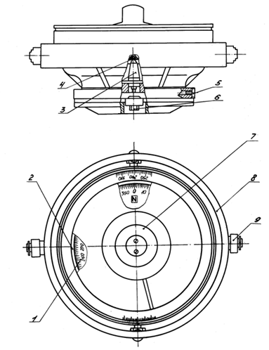
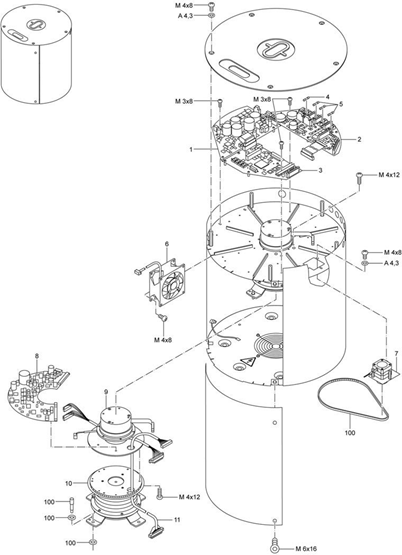
Typical view of a compass bowl, using UKPM-M as an example

1 – MCE; 2 – heading indicator; 3 – column; 4 – hairpin;
5 – plug for refilling; 6 – plug; 7 – illumination unit;
8 – cardan suspension; 9 – roller bearings.

Магнитные компасы

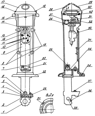
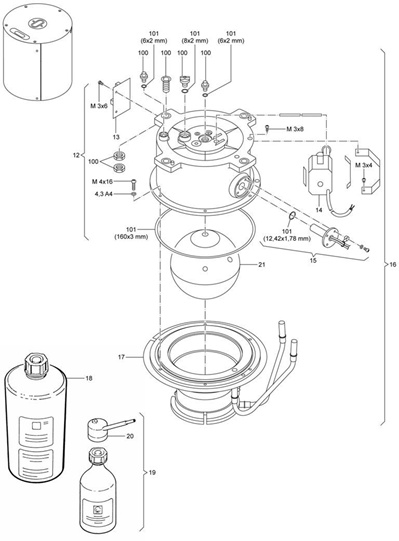
Typical view of a binnacle with a pot installed, using the example of the KM145-S compass


1 – optical device
2 – remote control
3, 14 – backlight brightness control
4, 6, 13 – switch
5 – indicator

7 – binnacle

8 – latitudinal deviation compensator

9 – cover

10 – deviation device

11 – locking screws
12, 31 – lamps
15 – quarter deviation compensator
16, 19 – bracket
17 – cap
18, 24 – scale
20 – toggle switch
21 – oil seal
22 – base
23, 39 – handles
25, 26 – lenses
27 – protective glass

28, 29 – windows
30 – course converter
32, 37 – connector
33 – deviation device
34 – box with silica gel
35 – heating glass
36 – holes
38 – mirror
40 – electromagnetic deviation compensator.


binnacles

Depending on the type of vessel on which the binnacle is installed, one of two types can be used: A1 or A2. The characteristics of both types are given below.

Combinations of magnetic compasses and binnacles are shown in the table:

Magnetic compass

Binnacle

Class A

Type A1

Type A2

Class B

Type A1

Type A2

Binnacles type A1

The Type A1 binnacle must be of such a height that the magnets of the compass sensing system are at least 1 m above the bottom surface of the binnacle cushion on the deck.

Binnacles type A2

Type A2 binnacles are used in navigation when the design of the vessel excludes the possibility of installing a full-size binnacle.

Lighting

The binnacle must have suitable arrangements for illuminating the horn and traverse from the ship's electrical network and from an emergency light source. In the binnacles of reflective and projective compasses, a clear image must be visible from the helmsman's position.

A device must be provided to adjust the intensity of light from the ship's electrical network.

Electrical lamps, fittings and electrical wiring must not affect the sensitive system.

Accuracy of bow and stern marks

To ensure accuracy during installation, bow and stern marks must be provided and must be within 0.5° (1.0° for Class B compasses) from the axis of the bow and stern gimbal trunnions.

Transmission of course readings from the card in the bowler can be carried out optically using an optical periscope, or using an optical light guide (in cases where the binnacle and the receiving screen of the periscope are not located coaxially), as well as using an induction (or magnetic) sensor. Receiving course data can be broadcast to repeaters using course broadcast devices.

To ensure the ability to read course readings in any lighting conditions, the compass bowl is backlit


Liquids CASSENS & PLATH:

· 39012 (alcohol): Jupiter, Venus, Merkur

· 13310 (alcohol-free): Cassens type 11, 12, 21 (reflecta), SAURA, KEIKI


MAGNETIC COMPASS

Requirements

The magnetic compass must provide an indication of the ship's course with accuracy:

±1° on the move in the absence of pitching;

±5° when rocking in all directions up to ±22.5° with a period of 6 - 15 s.

The magnetic compass card must provide the ability to take readings with an accuracy of 0.5°.

The division value of the card should be no more than 1°.

Stagnation of the magnetic compass card with the horizontal component of the induction of the Earth's magnetic field at the location where the compass is installed H, µT, and ambient temperature

±20±3 °C should not exceed (3/Н)° after the card deviates from the magnetic meridian by ±2°.

The magnetic compass must be provided with appropriate means to ensure the stability of the card during ship vibrations and maintaining the normal position of the vertical axis of the compass bowl under operating conditions.

The bowl of a gimbaled compass must remain horizontal when the binnacle is tilted up to 45° in any direction. The pot must remain free when the pot is tilted in any direction at an angle of at least:

10° - for a compass with a gimbal;

30° - for a compass without a gimbal.

A magnetic compass must have devices to compensate for constant, semicircular, quarter, roll and latitudinal deviation.

If the ship is equipped with a demagnetization device, the magnetic compass must have an electromagnetic deviation compensator.

Each device must provide compensation for the corresponding deviation with an accuracy of +0.2°.

The design of the devices provided for in 5.2.6 must provide such deviation compensation that the residual deviation values ​​do not exceed ±3° for the main magnetic compass and ±5° for the spare one.

A magnetic compass must have a binnacle and electric illumination of the card, sufficient for clear visibility of the card divisions. It must be possible to adjust the light intensity.

Electrical lighting of the compass card must be provided from the ship's power plant and an emergency source of electrical energy.

Power from an emergency source of electrical energy can be replaced by power from a battery.

The height of the main compass binnacle must be such that, together with the cushion on which it is installed, the glass plane of the compass bowl is at a height of at least 1300 mm from the deck. The highest installation height of the compass is not regulated, but in all cases it should not exceed the value that ensures ease of use of the compass.

The main compass must be equipped with a direction finder, which must provide direction finding of landmarks, objects and celestial bodies visible from the ship with a reading accuracy of ±0.5°.

Direction finders of a new design must provide a direct bearing reading.

It must be possible to clearly take a reading from a magnetic compass card or optical periscope at a distance of at least 1.4 m, both in daylight and in artificial light. The use of magnifying agents is allowed.

A magnetic compass with remote electrical transmission of heading must meet

requirements of 5.2.1 - 5.2.10 rules and, in addition, ensure the transmission of information about the true course to other navigation equipment and repeaters (see also 5.10 rules).

Rules for equipment of sea vessels V-62

A magnetic compass with remote electrical transmission of heading may consist of:

.1 a magnetic compass that does not require a sensitive element of electrical power for operation and is equipped with a device for remote electrical transmission of heading.

If the remote electrical transmission of heading complies with the requirements of 5.10 rules, such a compass can be used as the main magnetic compass;

.2 an electromagnetic compass requiring electrical power to operate the sensing element and equipped with an electronic device for generating a compass course with corrections and transmitting it to other navigation equipment.

This compass can be used on ships as an additional magnetic compass to the main compass.

The magnetic compass must be equipped with devices to compensate for deviation within the following limits:

.1 vertical component of the ship’s magnetic field induction at the compass installation site, causing heel deviation, _ up to +75 µT;

.2 coefficient A - up to ±3°;

.3 coefficient B - up to ±(720/N)°;

.4 coefficient C - up to ±(720/N)°;

.5 coefficient D - up to ±7°;

.6 coefficient E - up to ±3°,

where H is the horizontal component of the induction of the Earth's magnetic field at the location of the compass, µT.

The established positions of the regulators of electronic deviation compensation devices must be clearly marked and remain in effect at all times.

The deviation compensation device must be protected from unauthorized

access.

A magnetic compass with remote electrical heading transmission must have at least one output channel for transmitting heading to other navigation equipment in accordance with IEC 61162.

A magnetic compass with remote transmission of compass heading must remain operational during the following changes in the ship's movement:

circulation at angular speed up to 68/s;

yaw with a period of 10 - 20 s and the largest deviation from the course by +5°.

The design of a magnetic compass with optical remote transmission of card readings must provide on the screen a direct reflected image of a sector of the card’s scale with clearly visible degree divisions on an arc of at least 30°, as well as a heading line mounted in the compass casing.

It is recommended to provide a device for obtaining an image of the card scale from the stern and bow sides of the periscope.

The length of the periscope of the optical path of a magnetic compass with optical remote transmission of card readings must be such that when installing the compass on a cushion, taking into account the passage of the periscope pipe through the deck of the ship, the screen could be installed at eye level of the helmsman.

A device must be provided to adjust the height of the screen 100 - 150 mm up and down from the middle position.

The screen must be equipped with a means that protects it from bright sunlight or other light that can cause the image on the card screen to become overexposed. The image on the screen must be clearly visible during the day and at night.

The design of the optical path and screen must be such that the image of the sector of the card’s scale remains clear and clear during visual direction finding and with the compass cover closed.

Rules for the equipment of sea vessels V-63

A device for adjusting and fixing the screen position must be provided.

The optical path must be waterproof (IP56). Measures must be provided to prevent sweating of the path and condensation of moisture in it, and easy access to the optical system for its maintenance must be ensured.

The boat magnetic compass must meet the following requirements:

.1 the division value of the compass card must be 1°, 2° and no more than 5° depending on the diameter of the card;

.2 stagnation of the compass card under conditions should not exceed (9/N)°;

.3 illumination of the card must be provided in accordance with 6.13.8.1.5, Part II

"Life-saving equipment";

.4 a device must be provided for attaching the compass to the boat, as well as a case for storing it;

.5 the diameter of the card must be sufficient for normal reading.

The composition of navigation instruments, devices and instruments that must be installed on the ship or with which the ship must be equipped is determined depending on its gross tonnage, taking into account the navigation areas and the purpose of the ship in accordance with Table. 2.2.1. Definitions of navigation areas are given in 1.2 of Part I “Regulations on Surveys”.

Table 2.2.1 (regarding magnetic compasses)

No.

p/p

Navigation equipment

Quantity for ships of gross tonnage

Explanations

<150 1

5150 1

5300

5500

53000

510000

5 50000

1

Main magnetic compass 2

1

1

1

1

1

1

1

The compass kit must include a direction-finding device that provides bearings along a 360° arc of the horizon and is independent of any source of electrical energy

2

Magnetic spare compass

1

1

1

1

1

1

Should be interchangeable with the main magnetic compass. Not required if full duplication of the main magnetic compass is ensured (see note 6)


1 The composition of navigation equipment for passenger ships with a gross tonnage of less than 500 should be determined according to column 3 (5300) of the table, and the requirements of paragraphs 15 and 20 of the table should be taken into account.

2 Remote transmission of the main magnetic compass readings to the main steering position must be provided.

2. On ships, the construction contracts of which were signed on or after January 1, 2007, a gyroscopic compass is allowed to be used as a spare magnetic compass, which must be powered from the main and emergency sources of electrical energy, as well as from a transitional source that can be a rechargeable battery. Moreover, such a gyroscopic compass cannot be considered as required by paragraph 7 of this table in relation to ships with a gross tonnage of 500 or more.

2.2.1 Navigation equipment required according to table. 2.2.1 may be replaced by another, newly invented, developed or modernized, provided that it is equivalent in purpose, has the required or better operational and technical characteristics and is approved by the Register.

2.2.2 Navigation equipment not provided for in this part may be allowed to be installed on ships as additional equipment, provided that its placement and operation will not create difficulties when working with the main navigation instruments, affect their readings and reduce the safety of navigation.

Navigation equipment installed on the ship in addition to the main equipment provided in Table. 2.2.1, must be of a type approved by the Register and must meet the operational and technical requirements for the main equipment.

Magnetic compass with remote transmission of compass heading must remain

operable under the following changes in the ship's movement:

circulation at angular speed up to 68/s;

yaw with a period of 10-20 s and the largest deviation from the course at +58°.

5.2.16 Design of a magnetic compass with optical remote transmission of readings

The card must provide on the screen a direct reflected image of a sector of the card's scale with clearly visible degree divisions on an arc of at least 308, as well as a heading line fixed in the body of the compass bowl.

It is recommended to provide a device for obtaining an image of the card scale from the stern and bow sides of the periscope.

5.2.17 The length of the periscope of the optical path of a magnetic compass with optical remote transmission of card readings must be such that when installing the compass on a cushion, taking into account the passage of the periscope pipe through the deck of the ship, the screen could be installed at eye level of the helmsman.

A device must be provided to adjust the height of the screen 100-150 mm up and down from the middle position.

5.2.18 The screen must be equipped with a means that protects it from bright sunlight or other light that can cause the image on the card screen to become overexposed. The image on the screen must be clearly visible during the day and at night.

5.2.19 The design of the optical path and screen must be such that the image of the sector of the card’s scale remains clear and clear during visual direction finding and with the compass cover closed.

5.2.20 A device for adjusting and fixing the position of the screen must be provided.

5.2.21 The optical path must be waterproof (IP56). Must be

measures are provided to prevent sweating of the path and condensation of moisture in it, and easy access to the optical system is provided for its maintenance.

THE BOAT MAGNETIC COMPASS MUST MEET THE FOLLOWING REQUIREMENTS:

.1 the division value of the compass card must be 1, 2° and no more than 5° depending on the diameter of the card;

.2 stagnation of the compass card under the conditions set out in 5.2.3 should not exceed (9/N)8;

.3 illumination of the card must be provided in accordance with 6.13.8.1.5, Part II “Life-saving appliances”;

.4 a device must be provided for attaching the compass to the boat, as well as a case for storing it;

.5 the diameter of the card must be sufficient for normal reading.

RECOMMENDATIONS FOR INSTALLING MAGNETIC COMPASSES

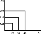
1. It is recommended to install magnetic compasses in such a way that the distances from the center of the compass bowl to the magnetic materials included in the ship structures are no less than those given in table. 1-1 and 1-2.

2. All metallic magnetic materials should be positioned as symmetrically as possible relative to the magnetic compass.

3. The distance from the center of the magnetic compass bowl to the deck or ceiling made of magnetic materials must be at least 1 m, while it must be taken into account that the distances from the ends of bulkheads and deck decks in this case must be no less than those specified in table 1-1.

4. Magnetic compasses should not be installed at a distance less than 2 m from each other. For vessels less than 60 m in length this distance may be reduced to 1.8 m.

Table 1-1

The shortest distances from a magnetic compass to metal ship structures made of magnetic materials depending on the length of the vessel

Distance from stationary materials,

m

Distance from moving magnetic materials and materials with a changing magnetic field, m

With

Maximum length of the vessel,

m

up to 30

40

50

60

70

80

83 and

more

up to 30

40

50

60

70

80

90

100

110

120 and

more

1.5

1.75

2.1

2.3

2.7

2.9

3.0

2.0

2.2

2.4

2.6

2.9

3.1

3.4

3.5

3.7

4.0

Notes: 1. Movable magnetic materials are considered to be davits, fan pipes, doors, cargo booms and other movable elements of the ship's structure made of magnetic materials.

2. Materials with a changing magnetic field are exhaust pipes, chimneys and other heating devices made of magnetic materials. Ship pipe casings are considered immovable magnetic material.


Table 1-2

The shortest distances from a magnetic compass to metal ship structures made of magnetic materials for fishing vessels and vessels of a limited navigation area with a maximum length of up to 60 m

Distance from magnetic materials, m, depending on the maximum length of the vessel,

up to 20

thirty

40

50

60

1.1

1.3

1.5

1.7

2.0


RECOMMENDATIONS FOR DETERMINING THE “SAFE DISTANCE” FOR A MAGNETIC COMPASS

1. All shipboard equipment must be marked to indicate the minimum distance at which the equipment may be installed from the magnetic compass.

This smallest distance is considered a “safe distance” if the equipment’s magnetic fields do not distort the magnetic compass readings by more than 0.045 °/N, where H is the horizontal component of the Earth’s magnetic field, Oe (oersted).

2. The determination of the “safe distance” must be made for each type of equipment in the following three ways:

.1 by measuring the distance from the nearest point of the equipment to the center of the magnetic compass, when the magnitude of the deviation of the magnetic compass card as a result of the influence of the magnetic field created by the equipment will be equal to the value determined by the relationship given above. In this case, the equipment must be in the form in which it is usually installed on the ship;

.2 by measuring the distance after magnetizing the equipment in a field of 1.5 Oe created by direct current and additionally applying a stabilizing alternating current field of 18 Oe (rms value).

In some cases, the application of an alternating magnetic field is not permitted, as this may damage the equipment.

Equipment should be magnetized in such a way that the greatest result from magnetization is obtained (for example, along the longest axis of equipment made of magnetic material);

.3 by measuring the distance, as specified in 2.1, from equipment that is electrically powered and in operating condition.

3. The greatest distance that is obtained by comparing the three measurements above should be taken as the “safe distance”.

4. The “safe distances” specified in the Recommendations apply to equipment installed near the magnetic compass of ships with an unlimited navigation area.

5. For compasses of ships of a limited navigation area with a length of less than 60 m, the “safe distance” may be reduced by 25%.

The compass card must have 360° graduations (1° divisions) starting from north in a clockwise direction when viewed from above. Every 10th degree must be marked with three corresponding numbers. North must also be marked "000". The main directions must be marked with capital letters N, S, "E" and W; intermediate points can also be marked. Alternatively, the North point may be indicated by a suitable symbol.

Graduation of the card

Magnetic compass

Cartridge division price

Card numbering

Class A

Every 10°

Class B

No more than 5°

At least every 30°


If the card is graduated on both sides, then the discrepancy between the divisions should not exceed 0.2°.

The diameter of the compass card for various types of binnacles is shown in the table.

Magnetic compass

Binnacle type

Card diameter, mm

Class A

A1

>165

A2

>100

Class B

A1

>50

A2

>50

Notes

1 The binnacle type A1 (see 5.1) is determined by its height, which should not be less than 1 m; if less than 1 m, then it is a type A2 binnacle (see 5.2).

2 The diameter of the magnetic compass card for a lifeboat/rescue boat is given in H.2.1.


SIGNS OF UNSATISFACTORY CONDITION AND UNRELIABLE OPERATION OF THE MAGNETIC COMPASS:

1. The presence of an air bubble in the compass pot. If the size of the air bubble is more than 25 - 30 millimeters, then the compass must be taken to a workshop for inspection.

2. The liquid has lost its transparency and has a color (yellowish, greenish, grayish or simply darkened).

3. The presence of sediment or suspended particles in the liquid.

4. From numerous turns of the compass card, as well as from vibration and shocks caused by slamming and pitching and rolling of the vessel, the agate (in some foreign compasses, sapphire - blue agate) firebox wears out. For example, under normal operating conditions, a sapphire firebox wears out in two years, and in more severe conditions, with frequent shocks and strong vibration, the firebox wears out in less than two years.

5. If there is stagnation of the compass card. You can check it as follows. Bring the magnet to the compass and, moving it near the compass, tilt the card 90° to the left or right and remove the magnet from the compass to a safe distance. The card should return to its original position within 1° in approximately 56 seconds. In different areas, the return time for the card may differ from the specified one. An experienced navigator, even without a magnet, will determine the stagnation of the card only by observing how the card behaves when the ship changes course.

6. When determining the compass correction, the calculated actual deviation differs from the tabulated one (provided that the table was compiled by a licensed deviator and no later than two years ago):

— at the main magnetic compass by more than 3°;

- at the track by more than 5°.

7. It is difficult to swing the compass bowl in one or two gimbals.

8. There is excessive wear or damage at the gimbal mounting points at the top of the magnetic compass binnacle.

9. The reading of the magnetic compass through the prismatic periscope is difficult to discern due to contamination of the lenses and mirrors or improper installation of the lens in the binnacle (it can be installed with the reverse side - “upside down”).

10. There is no or insufficient illumination of the compass reading, main and/or backup lighting.

11. The table of residual deviation compiled by the deviator was compiled more than two years ago or is completely missing.

Liquids CASSENS & PLATH:

13310: Jupiter, Venus, Merkur

39012 (alcohol): Cassens type 11, 12, 21 (reflecta), SAURA, KEIKI

UKPM-M, KMO-T

The kettle is filled with non-toxic liquid: distilled water GOST 6709 – 0.24 kg, distilled glycerin GOST 6824 – 0.04 kg, ethyl alcohol GOST R 51652 – 0.52 kg

KM-145M

distilled water GOST 6708 – 16%; distilled glycerin GOST 6824 – 5%; rectified ethyl alcohol GOST 5962 – 79%.

When working with compasses made in Russia (USSR), the type of supporting fluid can be either alcohol-containing or PMS-5.

The exact type of supporting fluid can be clarified in the technical documentation of the compass, and according to the tag on the pot.

If there is no technical documentation on board, most of the instructions can be obtained from the link: http://www.kipz.ru/nav_ru.htm


Classification of faults and general information on the theory of failures

Malfunctions and methods for finding them

A faulty state (malfunction) is a condition of an object in which it does not meet at least one of the requirements established by the regulatory and technical documentation.

Классификация неисправностей и общие сведения по теории отказов

a malfunction in which at least one of the main parameters falls outside the established operational tolerance. The immediate consequence of the main fault is failure, i.e. complete or partial loss of system functionality.

if the product does not meet at least one of the requirements established for minor parameters. Minor faults do not affect the functionality of the product, i.e. do not lead to failures.

Классификация неисправностей и общие сведения по теории отказов

Electrical circuit malfunctions

Mechanical transmission faults

Break

Complete absence of engagement (connection)

Significant increase in resistance

Incomplete connection

Significant reduction in resistance

Transmission braking

Short circuit

Gear jam

Changing element reactivity

Changing the moments of inertia in the transmission


Causes of breaks in electrical circuits:

aging of elements (break in resistance)

passage of increased currents

· blows

vibration

· corrosion

In the event of a break, the signals at the output of the product (object) disappear, and sometimes the supply voltage increases.

Significant increases in resistance occur due to the aging of elements and changes in their parameters. In this case, the signals at the output of the circuits are distorted or completely disappear.

A decrease in resistance in electrical circuits is associated with a decrease in insulation resistance, an increase in surface leaks, aging of elements, etc. As a rule, in these cases, overloads of power supplies occur, increased heating of the elements, and blown fuses.

Short circuits occur due to insulation breakdowns, short circuits of conductors and elements to the housing, etc. Short circuits are accompanied by overloads of circuit cascades and power supplies. Signs of a short circuit: disappearance of output signals; the appearance of sparks, smoke and the smell of burning insulation; severe overloads, tripping of protection devices.

Классификация неисправностей и общие сведения по теории отказов

failure of alarm lamps, fuses, resistors, transformers

short-term malfunctions in the operation of objects, changes in the resistance value of resistors, capacitors, current parameters of semiconductor elements, etc.


Due to the complex nature of failures, there is a broad classification of them. Failures are classified as follows:

a) By the nature of the change in parameters until the failure occurs:

1. Sudden, characterized by abrupt changes in several specified parameters of the object;

2. Gradual, caused by a gradual change in the values ​​of one or more specified parameters of the object)    

       b) By relationship with each other on:

1. dependent, when the failure of an object element is caused by the failure of another element;

2. independent - the failure of one element is not caused by the failure of another element of the object.

c) By the nature of the time of disruption to:

1) failure - a self-correcting failure leading to a short-term disruption of the functionality of the object;

2) intermittent - a failure of the same nature that occurs repeatedly.

d) For reasons arising from:

1) structural - a failure arising as a result of violation of established rules or norms for the design of
an object;

2) production - a failure that arose due to a violation of the established technological process of manufacturing
or repairing an object;

3) operational - a failure resulting from a violation of established rules or operating conditions
of the facility.

Failures that occur as a result of an unexpected deviation of the external operating conditions of an object from the calculated ones or during prolonged exposure to any external destructive factor are classified as failures due to external influences.

Due to the fault of the crew, failures occur due to violation of operating rules, due to insufficient training and weak (lost) skills in operating equipment, sometimes due to indiscipline or negligence.

When performing troubleshooting work, you must adhere to certain rules. Search technology can be divided into the main operations indicated in the diagram


Классификация неисправностей и общие сведения по теории отказов

Regardless of the means used, the troubleshooting process has two stages:

1) selecting the sequence of checking elements

2) choice of methodology (method) for carrying out individual verification operations.


The search can be carried out according to a predetermined sequence of checks, or the progress of each subsequent check is determined by the result of the previous one.

Классификация неисправностей и общие сведения по теории отказов

The choice of one or another sequence of checks depends on the design of the products as a whole or their part in which the malfunction occurred, and can change in the process of accumulating information on the reliability and labor intensity of checking the elements.

The method of sequential element-by-element checks is that when troubleshooting, product elements are checked one by one in a certain, pre-established sequence.

1. If the next element being checked turns out to be serviceable, then proceed to checking the next element.

2. If a faulty element is detected, the search stops and the element is replaced (repaired).

3. Then the object is checked for functionality. If the object (system) does not function normally, then proceed to further testing.

4. Moreover, the check begins from the position at which the faulty element was detected.

5. If a second faulty element is detected, it is also replaced or repaired (restored), and the object is again checked for operability.

6. If the object is not functioning normally, the search is resumed again, and so on until the object or system is functioning normally.

Классификация неисправностей и общие сведения по теории отказов

The simplest example of using this method can be troubleshooting in the automatic control system of one of the process parameters. First the regulator is checked, then the actuator, then the amplifier, etc. Thus, the object is identified, the malfunction of which caused the disruption of the normal functioning of the equipment.

When, for example, a malfunction is detected in an actuator, the element-by-element structure of this device (object) is considered. Let us assume that an electromechanical drive is used as an actuator, representing a DC electric motor, a coupling (for example, a friction clutch) and a gearbox


Классификация неисправностей и общие сведения по теории отказов

Here you can set the following sequence of checking elements: 1-2-3-4-5-6-7-8. the most vulnerable of them may be elements 1,2,4,7 and 8. Therefore, when using the element-by-element verification method, there are two possible ways to sequence the control of elements. If a product (system) uses elements whose test duration is approximately the same, then the test should begin with the elements that have the least reliability. For our case, these are elements 1,2,4. If the reliability of the elements of a given product is approximately the same, then it is advisable to start testing with the element that requires the least time to test. For example, from protective device 1; then 2; then 4. To successfully use these rules, it is necessary to know not only the functional and schematic diagrams of objects and systems, but to have a clear understanding of the reliability of their elements.

The method of sequential group checks is that all elements of an object, taking into account their functional connections, are divided into separate groups and the serviceability of each group as a whole is monitored.

1. The sequence of inspections is determined by the result of the previous inspection.

2. As inspections are carried out, the number of elements to be inspected decreases.

3. At the last stage of control, there must be one element in the group.

An example of troubleshooting using this method is shown in the functional diagram of the system in the figure.

Классификация неисправностей и общие сведения по теории отказов

The scheme is divided into groups I-VIII. The structure is then split into two subgroups, and so on. In this case, the sequence of checks will be as follows:

a) The signal at point 4 is monitored. If it is normal, then go to point 6, because it is assumed that the faulty element is in group V, VI, VII, VIII. If the signal at point 4 does not correspond to the norm, then the signal at point 2 is checked, because one of the elements I, II, III, IV is faulty. If the signal at point 2 is normal, then elements I and II are serviceable, and point 3 should be checked. This will reveal which of elements III or IV is faulty.

b) If, when monitoring points 4 and 6, the signal corresponds to the required parameters, then point 5 is monitored, as a result of which the faulty element V or VIII is determined.

With this method of troubleshooting, it is necessary to know the parameters of the signals at the control points, as well as the types of measuring instruments and the rules of their operation.

· If there are several faults in an object (system), the fault finding scheme will not change. Moving along one of the branches of the structure, they inevitably come to one of the faulty elements. After eliminating this malfunction (restoring the element), the operability of the object is checked, which will show whether the malfunction still exists or not.

· If there is a fault, the search process continues (repeats), which should lead to a second faulty element, etc.

· This method is also called the midpoint method. However, in the general case, the number into which the structural diagram of an object (system) is divided may not be equal to two. It is necessary to break down the system, taking into account the functional connections of individual elements and the reliability of their operation.

·         

Group inspection method.

a distinction is made between checks “with exception” and “without exception”.

· Checking “with exception” means that a conclusion about the operability of one of the groups of elements is made based on checking other groups.

For example, we have three groups of elements. Based on the test results, the serviceability of groups 1 and 2 was established. Without checking, we conclude that the faulty element is in the 3rd group.

· During “no exception” checks, the performance of all groups is monitored. At the final stage, a “no exceptions” check is always carried out, which eliminates the possibility of error.


List of main cables and wires used on inland and mixed (river-sea) navigation vessels

Brand

Design

Application

KMPV, KMPVE, KMPEV, KMPVEV, KMPEVE

Cables with polyethylene insulation are intended for installation of control circuits, alarms, communications, inter-device connections operating at rated alternating voltages of 500 and 1000 V with a frequency of no more than 200 kHz or, respectively, at constant voltages of 750 and 1500 V in the temperature range from -50ºС to +65ºС. Cables with polyvinyl chloride insulation are intended for power and lighting networks and control circuits for a rated alternating voltage of 500V with a frequency of no more than 400 Hz or 750V DC in the temperature range from -50ºС to +65ºС. The cables are manufactured in climatic version B in accordance with GOST B 20.39.404-81. The cables are flame retardant, the cables are non-toxic within operating temperatures, the cables (except for KMVVE-D) are resistant to the effects of fuels and lubricants and PGV liquid. Linear shrinkage of core insulation from heating during soldering is no more than 3 mm.

Перечень основных кабелей и проводов, применяемых на судах внутреннего и смешанного (река-море) плавания

KMPV

Cables with copper conductors with polyethylene insulation, in a polyvinyl chloride sheath

In control circuits, signaling and inter-device connections, in power and lighting networks at voltages up to 500 V AC and up to 750 V DC: for fixed installation indoors and on the open deck, subject to protection from direct influence

solar radiation and sea water


Brand

Design

Application

KMPVEV

Cables with copper conductors with polyethylene insulation, in protective polyvinyl chloride

shell

Same as KMPV

KMPEV

Cables with copper conductors shielded, partially shielded or shielded in pairs with polyethylene insulation, in polyvinyl chloride

shell

Same as KMPV

KMPEVE

Cables with copper conductors shielded, partially shielded or shielded in pairs with polyethylene insulation, in polyvinyl chloride

shell, in a common screen of copper wires

Same as CMPV, including in places where cable shielding is required

KMPEVEV

Cables with copper conductors shielded, partially shielded or shielded in pairs with polyethylene insulation, in a protective polyvinyl chloride sheath, in a general screen of copper wires

The same as in CMPV, including in places where mechanical stress is possible

PRC, CNRE, CNRP, CNRU

Ship cables with copper conductors, with rubber insulation, in a rubber or lead sheath, shielded or unshielded, are intended for fixed installation and connection to movable current collectors operated on naval vessels of an unlimited navigation area, river fleet, coastal and floating structures. The cables are designed for operation at alternating voltage up to 690 V with a frequency of up to 400 Hz or a direct voltage of 1200 V, as well as for transmitting low-power electrical control signals of alternating voltage up to 400 V with a frequency of up to 1200 Hz or 500 V direct voltage. The cables are resistant to vibration loads and single shock loads. The cables are resistant to sea water, as well as periodic exposure to lubricating oils (total exposure time - 300 hours), diesel fuel (total exposure time - 100 hours) and solar radiation (total exposure time - 240 hours). Cables do not spread flame when laid alone.

Перечень основных кабелей и проводов, применяемых на судах внутреннего и смешанного (река-море) плавания


Brand

Design

Application

China

Shell made of oil-resistant rubber,

flame retardant

In power and lighting circuits, in control circuits, signaling and inter-device connections; for fixed installation indoors and on an open deck, subject to protection from direct exposure to solar radiation, including when exposed to radial hydrostatic pressure up to 1.96 MPa (20

kgf/cm2)

CNRE

Cable with rubber insulation in a sheath of oil-resistant rubber that does not propagate combustion in a common screen of tinned copper wires

CNRP

Shell made of oil-resistant, flame retardant rubber, protective braided steel

galvanized wires

In power and lighting circuits, in control circuits, signaling and inter-device connections; for fixed installation indoors and on an open deck, subject to protection from direct exposure to solar radiation, including exposure to radial hydrostatic pressure up to 1.96 MPa (20 kgf/cm2). Including in places where it is possible

mechanical influences

KNRU

Shell made of oil-resistant, flame retardant rubber, reinforced

KPRK, KNREk

Marine cables with copper conductors with rubber insulation, sheathed in polyvinyl chloride plastic, shielded or unshielded, are intended for fixed installation on naval vessels of unlimited navigation area, river fleet, coastal and floating structures. The cables are designed for operation at alternating voltage up to 690 V with a frequency of up to 400 Hz or direct voltage 1200 V and for transmitting low-power electrical control signals of alternating voltage up to 400 V with a frequency up to 1200 Hz or 500 V direct voltage. The cables are resistant to vibration loads and single shock loads. The cables are cold-resistant. Resistant to sea water and 20% salt solution, as well as periodic exposure to lubricating oils (total exposure time - 300 hours), diesel fuel (total exposure time - 100 hours) and solar radiation (total exposure time - 100 hours)

exposure – 240 hours). Cables do not spread flame when laid alone.


Перечень основных кабелей и проводов, применяемых на судах внутреннего и смешанного (река-море) плавания

China

PVC shell

plastic compound

In power and lighting networks, in control circuits, signaling and inter-device connections; for fixed installation indoors and on an open deck, subject to protection from direct exposure to solar radiation, incl. under conditions of exposure of the cable to vapors and condensate of oils and fuels, vapors of acids, alkalis, apatite, coal, cement and other dust, fish meal and other fish products in the conditions of fish processing shops and refrigerated rooms, as well as when exposed to radial hydrostatic

pressure up to 1.96 MPa (20 kgf/cm2)

KNREc

A copper wire screen located between two PVC shells

RG213, RG214/U, RG223, RG58, RG59

RG213

Cable with copper conductors with polyethylene insulation, in a polyvinyl chloride sheath. Nominal characteristic impedance 50 Ohm

For transmitting radio frequency signals. Used for installing VHF and MF/HF antennas and satellite communications on sea, river and mixed navigation vessels.


Brand

Design

Application

RG214/U

Cable with copper conductors, screen made of silver-plated copper braid.

Nominal characteristic impedance 50 Ohm

For transmitting radio frequency signals. Used for installing VHF and MF/HF antennas and satellite communications on sea and river vessels.

and mixed swimming

RG58

Cable made of copper, dielectric made of foamed polyethylene with braided tinned copper.

Nominal impedance 50 Ohm.

For transmitting radio frequency signals. Used for installing GNSS antennas on sea, river and mixed navigation vessels. For

operation in difficult climatic conditions

RG59

Cable made of steel, dielectric made of foamed polyethylene with braided tinned copper.

Nominal characteristic impedance 50 Ohm

For transmitting radio frequency signals. Used for installing GNSS and overlay antennas on sea, river and mixed vessels.

swimming and overlay


Cable connectors most commonly used for radio and navigation devices

N-type connector

Кабельные разъемы, которые наиболее часто используются для устройств радио и навигации

Mostly, connectors of this type are used in the 50 Ohm version, but there is also a 75 Ohm version. In practice, it is recommended to use this channel on flexible cables (with an outer conductor - braid) and cables up to 12 mm in sheath with external conductor in the form of foil. span>


TNC connector

Кабельные разъемы, которые наиболее часто используются для устройств радио и навигации

The connector is used in measuring, low-power communication equipment (up to 50 W), as well as in household appliances (TVs, cordless telephones, etc.).


BNC connector

Кабельные разъемы, которые наиболее часто используются для устройств радио и навигации

The connector is used in measuring, low-power communication equipment (up to 50 W), as well as in household appliances (TVs, cordless telephones, etc.).


UHF connector

Кабельные разъемы, которые наиболее часто используются для устройств радио и навигации

PL-259 connector. They are mainly used for low-frequency (CB) communication equipment.


< span style="color: #333333;">DB-9F (Serial COM connector)

Кабельные разъемы, которые наиболее часто используются для устройств радио и навигации

This connector is used for programming equipment or where data transfer is required.

External Cable Overview, SAILOR 6000B A2 GMDSS Package, 150W - Incl. Console - DC Floating

External Cable Overview, SAILOR 6000B A3 GMDSS Package, 150W/2 x mini-C - Incl. Console - DC Floating

External Cable Overview, SAILOR 6000B A3 GMDSS Package, 150W/2 x mini-C - Incl. Console - DC Floating


External Cable Overview, SAILOR 6000B A4 GMDSS Package, 150W/2 x Radiotelex, mini-C - Incl. Console - DC Floating

External Cable Overview, SAILOR 6000B A4 GMDSS Package, 150W/2 x Radiotelex, mini-C - Incl. Console - DC Floating


SAILOR 6194 Indication and buttons

SAILOR 6194 Индикация и кнопки

Inmarsat network coverage area

INMARSAT (INMARSAT - International Maritime Satellite Organization) is an international organization that provides on a commercial basis its technical means for communication with mobile objects at sea, on land and in the air. Inmarsat communications are currently provided by three geostationary satellites (Inmarsat I4). Coverage of the entire globe is provided, with the exception of the polar regions. The card declared by the operator looks like this:

Зона покрытия сети Inmarsat

Registration of Fleetbroadband and Inmarsat

The question comes up very often. What to do after purchasing Inmarsat system equipment? It's simple! Just like a simple mobile phone, you need to connect to a provider and get your personal number. What should I do to register? Let's talk about the example of a Russian service provider - Federal State Unitary Enterprise

Morsvyazsputnik.

You will need the following documents:


If you are a ship owner registered in Russia:


1.        Inmarsat questionnaire - download https://cirspb.ru/download/Inmarsat.doc


2.        An extract from the Unified State Register of Legal Entities (USRLE), issued no later than 6 months and no earlier than 3 months from the date of conclusion of the agreement (original or copy certified by a notary);

3.        Power of attorney or other document confirming your authority

must be provided if you are not listed in the Unified State Register of Legal Entities;

4.        A copy of your passport - if you act as an individual;

5.        A copy of the individual entrepreneur’s state registration certificate - if you are an individual entrepreneur;

6.        Company details and bank details;

7.        A copy of the Certificate of Ownership of the vessel (chartering agreement);

8.        A list of persons using the terminal equipment of a legal entity, certified by an authorized representative of the legal entity, which indicates their last names, first names, patronymics, positions, telephone numbers, places of residence and details of the main identification document.

9.        A copy of the license for the ship's radio station or a copy of the expert opinion on the possibility of using radio-electronic equipment;

10.      A copy of the Certificate of the right to sail under the State flag.

11.      Equipment data (Individual certificate is desirable - RMRS Certificate) - the name of the equipment, manufacturer, type, serial number or ISN of the transceiver is required.

12.      Contract for the provision of communication services and settlement services - downloadРегистрация Fleetbroadband и Inmarsat

https://cirspb.ru/download/contract%20Inmarsat.doc


If you are a foreign ship owner:


1.        Inmarsat questionnaire - download http://cirspb.ru/download/Inmarsat.docРегистрация Fleetbroadband и Inmarsat

2.        A copy, certified by a natary, of the Certificate of Incorporation;

3.        A copy of the document confirming the authority of the person when concluding the agreement;

4.        Copy of passport – for individuals;

5.        A copy of the Certificate of Ownership of the vessel (chartering agreement);

6.        A list of persons using the terminal equipment of a legal entity, certified by an authorized representative of the legal entity, which indicates their last names, first names, patronymics, positions, telephone numbers, places of residence and details of the main identification document.

7.        Copy of license for sua commercial radio station or a copy of the expert opinion on the possibility of using radio-electronic equipment;

8.        A copy of the Certificate of the right to sail under the State flag.

9.        Equipment data (Individual certificate is desirable - RMRS Certificate) - the name of the equipment, manufacturer, type, serial number or ISN of the transceiver is required.

10.       Agreement for the provision of communication services and settlement services


You send this data to the FSUE email

"Morsvyazsputnik" marsat@marsat.ru. Then managers will begin work on your contract and questionnaire

For any questions, you can contact the employees of the Communications and Radionavigation Group of Companies or the employees of Morsvyazsputnik

Compatibility of satellite terminals with FELCOM antenna units

ADE

BDE

Antenna unit to be connected

FELCOM 18
(IC-118)

FELCOM 19
(IC-119)

FELCOM 15
(IC-115)

FELCOM 16
(IC-116)

FELCOM 18

OK

OK

OK

OK

FELCOM 19

NG*

OK

NG*

OK

FELCOM 15

NG**

NG**

OK

OK

FELCOM 16

NG*

NG**

NG*

OK


* There is a possibility of PRW
board failure **There is a possibility that the power will not be included

Compatibility of MF/HF with additional units

System

Control
Unit

Transceiver Unit

Antenna Tuning
Unit

406310B-00500

TT-6310B

SAILOR 6301
Control Unit
DSC Class Ad

SAILOR 6365 MF/HF 150W

SAILOR 6384 ATU

406311B 00500

TT-6311V

SAILOR 6366 MF/HF 150 W FCC

406320B-00500

TT 6320B

SAILOR 6368 MF/HF 250 W

406350B-00500

TT-6350B

SAILOR 6369 MF/HF 500 W

SAILOR 6383 ATU


a. An additional SAILOR 6301 Control Unit can be added.


System

Control
Unit

Transceiver Unit

Antenna Tuning
Unit

406310B-00500

TT-6310B

SAILOR 6301
Control Unit
DSC Class Ad

SAILOR 6365 MF/HF 150W

SAILOR 6384 ATU

406311B 00500

TT-6311V

SAILOR 6366 MF/HF 150 W FCC


406320B-00500

TT 6320B


SAILOR 6368 MF/HF 250 W


406350B-00500

TT-6350B


SAILOR 6369 MF/HF 500 W

SAILOR 6383 ATU


a. An additional SAILOR 6301 Control Unit can be added.

River frequencies

Table of river radio channels

·         Channel 5 - for calling ships, coordinating maneuvers and transmitting distress signals.

·         Channel 2 - for communication between ships.

·         Channel 3 - for communication with gateway dispatchers.

·         Channel 4 - for communication with other river fleet services.

·         Channel 25 and 43 - for communication between yachts


Simplex channels


River Canal No.

Frequency, MHz

No. River  canal

Frequency, MHz

No. River  canal

Frequency, MHz

41

300.025

5

300,200

63

336.125

2

300,050

61

336,025

24

336.150

42

300,075

22

330,050

64

336.175

3

300,100

62

336,075

25

336,200

43

300.125

23

336,100

65

336.225

4

300,150

Another option for flashing simplex channels, where (1)…(16) are the radio station channel numbers

No. River canal

Frequency, MHz

No.  River canal

Frequency, MHz

No. River  canal

Frequency, MHz

(1)    2

300,050

(7)  24

336.150

(13)  62

336,075

(2)    3

300,100

(8)  25

336,200

(14)  63

336.125

(3)    4

300,150

(9)  41

300.025

(15)  64

336.175

(4)    5

300,200

(10)  42

300,075

(16)  65

336.225

(5)   22

330,050

(11)  43

300.125


(6)   23

336,100

(12)  61

336,025


Rechflot communication channels in duplex mode

No. River  canal

Vessel

Coast radio station

Transmission frequency, MHz

Reception frequency, MHz

Transmission frequency, MHz

Reception frequency, MHz

6

300,250

336,250

336,250

300,250

46

300.275

336.275

336.275

300.275

7

300,300

336,300

336,300

300,300

47

300.325

336.325

336.325

300.325

8

300,350

336,350

336,350

300,350

48

300.375

336.375

336.375

300.375

9

300,400

336,400

336,400

300,400

49

300.425

336.425

336.425

300.425

10

300,450

336,450

336,450

300,450

50

300.475

336.475

336.475

300.475

eleven

300,500

336,500

336,500

300,500

71

300.025

336,025

336,025

300.025

72

300,075

336,075

336,075

300,075

73

300.125

336.125

336.125

300.125

      As can be seen from the tables, Some channels operate in simplex mode, i.e. reception and transmission are carried out at one frequency, and other channels operate in duplex mode - This is when the reception and transmission frequencies are separated. In simple terms, with duplex The ship's radio station transmits on the receiving frequency of the coast radio station, and The shore radio station transmits on the receive frequency of the ship's radio station. So This way both parties can talk and listen to each other at the same time.

Marine frequencies

For Marine VHF radio communications, a special frequency range of 156.0...162.025 MHz is allocated, in which radio exchange occurs using narrowband frequency modulation (NFM). The entire range is divided into 58 channels, the frequency grid step is 25 kHz.

All channels are divided into two subranges - channels with numbers 0..28 and 60..88. Within each subband, the frequency grid step is 50 kHz, the frequencies of the channels of the subbands differ by 25 kHz (except for channels 87B and 88B). For example, the frequency of channel 71 is 156.575 MHz, and the frequency of channel 11 is 156.550 MHz, the difference is 156.575-156.550 = 25 kHz (see table). For duplex channels, the frequency difference between the ship and shore radio stations is 4.6 MHz, and for simplex channels the frequencies are the same. For example, channels 0..7 are duplex, 8..16 are simplex. Most often, simplex channels are used for radio communication.

Channel number

Ship radio frequency, MHz

Coast frequency
radio stations, MHz

0

156,000

160,600

1

156,050

160,650

2

156,100

160,700

3

156,150

160,750

4

156,200

160,800

5

156,250

160,850

6

156,300

156,300

7

156,350

160,950

8

156,400

156,400

9

156,450

156,450

10

156,500

156,500

eleven

156,550

156,550

12

156,600

156,600

13

156,650

156,650

14

156,700

156,700

15

156,750

156,750

16

156,800

156,800

17

156,850

156.825

18

156,900

161,500

19

156,950

161,550

20

157,000

161,600

21

157,050

161,650

22

157,100

161,700

23

157,150

161,750

24

157,200

161,800

25

157,250

161,850

26

157,300

161,900

27

157,350

161,950

28

157,400

162,000

60

156,025

160.625

61

156,075

160,675

62

156.125

160.725

63

156.175

160,775

64

156.225

160.825

65

156.275

160,875

66

156.325

160.925

67

156.375

156.375

68

156.425

156.425

69

156.475

156.475

70

156.525

156.525

71

156,575

156,575

72

156.625

156.625

73

156,675

156,675

74

156.725

156.725

75

156,775

156,775

76

156.825

156.825

77

156.875

156.875

78

156.925

161.525

79

156,975

161,575

80

157,025

161.625

81

157,075

161,675

82

157.125

161,725

83

157.175

161,775

84

157.225

161.825

85

157.275

161,875

86

157.325

161,925

87B

161,975

161,975

88B

162,025

162,025

Channel 16 (156.8 MHz) is international and is used for calling ships and making distress calls.

Marine VHF radios range in power from 1 to 25 watts, giving a maximum range of 60 nautical miles (111 km) when using antennas mounted on tall ship masts or on coastal elevations. If radio antennas are installed on small ships low above the water, then the radio range will be 5 nautical miles (9 km). Antennas must be installed vertically, since vertical polarization of radio waves is used.

International Maritime Safety Information Service

Navarea. To unify the system for transmitting navigation and meteorological information in order to ensure navigation safety, the global navigation warning service NAVAREA has been developed, ensuring coordination of the transmission of navigation warnings by radio by all maritime countries.

This service provides for the division of the World Ocean into 16 geographical regions. Each area is assigned a coordinator - a country that collects, analyzes and transmits radio navigation information for this area in the form of warnings (Admiralty List of Radio Signals, Vol.3; ITU, List of Radiodetermination and Special Service Stations, List VI, Section 10, 11 ). Information is transmitted at least 2 times a day in English and national languages. Radio broadcasts are carried out in telegraph mode using class A1A radiation. Russia is the coordinator of the NAVAREA-XIII area.

Международная служба информации по безопасности на море


List of acts

Ship's acts - compiled in free form by the court's computer crew

1. Technical condition of electric drives of deck mechanisms (capstan, windlass) - indicate the brand of the engine and the available protections (zero, overload, etc.), a note on the last repair (extract from the construction/ship documentation)

2. Checking water level sensors in MKO and cargo holds - indicate the number and location of sensors, signaling method.

3. The technical condition of the generators of the main ship power station, a note on the latest repairs and maintenance.

4. List of drive electric motors for critical mechanisms (brand, quantity) - fire engines, ballast pumps, drainage pumps, steering gear drives, etc. (extract from construction/ship documentation)

5. Extract from the battery log on testing and maintenance of batteries. For maintenance-free batteries - a list with the main characteristics.

6. Table of equipment insulation resistance measurements

7. Measuring the voltage drop from the main switchboard to the farthest consumer

8. Check (visual inspection) of the dielectric mat


Acts of the repair company


1. Acceptance certificate and notifications for repair work

2. Certificate of inspection of lightning rods (resistance)

3. Statement of checking the condition of drive motors

4. Certificate of inspection of protection devices/circuit breakers (generators, energy distribution systems, electric motors, etc. powerful consumers)

5. Certificate of inspection of the main engine control system: APS, emergency engine stop with monitoring of sensor response parameters

6. Certificate of verification of the VDG control system: APS, emergency engine stop with monitoring of sensor response parameters

7. Oil content monitoring device (separator ~ water alarm)

8. Fire alarm and smoke detector

9. Fire alarm sensors (organization/crew verification instruments) with a list of sensors by beam

10. Instrumentation

                 - To check the instrumentation, a table-list of verification intervals is required.

11. Checking dielectric equipment and tools

Dielectric bots; Dielectric gloves; Pliers/round nose pliers/side cutters; Screwdrivers; Rugs; Voltage indicator (probe)

12. For oil tankers:

- certificate of oil/water control devices

- checking the condition of explosion-proof equipment by a certified laboratory

- SOTO and SAZRIUS calibration certificate

-Checking sensors as part of the automation system should include checking temperature sensors of cargo pump bearings


**Battery log must be present


Check the following navigation equipment


1. Magnetic compass (with residual deviation table)

2. Anemometer

3. Direction finder

4. Stopwatch

5. Barometer

6. Chronometer

7. Binoculars


Radio and navigation


1. Ship radio station license (see flag administration), + river license if available

2. Certificate of minimum crew size

3. Publications ITU, IAMSAR, Maritime Manual

4. GMDSS battery test report = residual capacity of at least 80%

5. EPIRB:

- Confirmation of registration in the Cospas/Sarsat system

- Annual inspection

- Last BTO

6. GMDSS equipment inspection report 6.3.22.2.

7. BTO agreement

8. Inspection reports:

- EPIRB

- AIS

- RDR/U-RDR (if any) – act and SOS


Not necessary (personal wishes of the engineer-inspector)


- SAR

- Wearable VHF

- Gyrocompass

- Magnetic compass

- Lag

- Echo sounder

- Radar

- KDVP


9. Confirmation of registration of SSOO with Morsvyazsputnik or other service provider and TEST with sending to 3 addresses

10. Confirmation of OSDR registration with Morsvyazsputnik or other service provider and initial TEST

11. Confirmation of registration and maintenance of EPIRB (capsule) RDR / U-RDR

12. Standard act on navigation charts and notices to mariners

Instructions for preparing to present the radio part to the RMRS inspection

Prepare copies of the following documents for delivery to the RMRS inspector:

1.     Report of annual technical inspection of EPIRB

2.     SAR annual technical inspection report

3.     Report on the annual technical inspection of VHF radio stations of life-saving equipment

4.     Certificate of verification of the residual capacity of GMDSS acid batteries (for ships presented for class)

5.     Certificate of verification of the operability of GMDSS equipment by a service organization (for ships submitted for class)

6.     Ship radio station licenses with attachment (if available)

7.     Certificate of compliance with TSC OSM

8.     Cover letter from the RMRS Inspectorate for approval of the project for installing new equipment

9.     RMRS Certificates for newly installed equipment


Preparation and procedure for presenting equipment to the RMRS inspector:

1.    Put the premises in order according to the management, including the battery room.

2.     Install the radio equipment of rescue equipment (EPIRB, SART, VHF r/stations) in their standard places. Regular locations of this equipment must be marked with international symbols. Prepare regulatory documents on radio communications.

3.     At the workplaces of operators of VHF, MF/HF r/stations, SZS "Inmarsat-S" (navigation bridge, r/wheelhouse) post action diagrams:

- transmitting a distress signal;

- to cancel a false distress signal;

- according to the algorithm of actions when receiving a distress signal in DSC mode.

4.     Check the state of charge of the GMDSS batteries and, if necessary, charge them.

During the annual survey, fulfill the requirements of paragraph 2.3.12 of Part IV “Radio Equipment” of the RMRS Rules for the Equipment of Sea-Going Ships, 2003, regarding the manufacture and installation of markings for batteries of GMDSS equipment.

5.     Connect standard terminals to the Inmarsat-S SZS and the MF/HF radiotelex r/station.


6.     One day before the test:

- conduct a Link test of the Inmarsat-S SES, print out the results on a printer for the RMRS inspector:

- make a call in DSC mode from the main VHF r/installation (using the DSC number assigned to the vessel) of the backup VHF r/installation, transfer confirmation of the call from the backup VHF r/installation to the main VHF r/installation;

- carry out an external check of the DSC MF/HF r/installation equipment by transmitting a test message to the Lyngby coast station (DSC ID 002191000).   The acknowledgment of receipt of the test message must contain the frequency on which it was received and the ship's DSC number.

- carry out control communication with the coastal r/center of the KMRP in ARQ mode, make a printout on the printer and save it for the RMRS inspector

- turn on the NAVTEX system receiver so that it receives several messages for mariners. Save the tape with the text of the messages for the RMRS inspector.


7.     On the inspection day, turn on all GMDSS and ELV equipment to be inspected.

8.     The verification procedure will proceed as follows. Upon arrival of the inspector, on his instructions, power will be removed from the GMDSS equipment from the on-board electrical network and the equipment’s functionality will be checked while the equipment is powered from batteries. Pay attention to the sound and light alarms when disconnected from the on-board network.

9.     For GMDSS equipment, be able to show in the equipment memory the results of checks of DSC equipment carried out the day before, perform an internal check of DSC equipment at the request of the inspector, show the settings of the MF/HF transmitter in the ranges of 2, 4, 6, 8, 12, 16 MHz.

10.   According to ERN devices:

- be able to work with the radar menu (switch from receiving ship speed data from GPS to log, etc.);

- show the alarm about dangerous depth in the navigation echo sounder

Frequency of inspections of GMDSS equipment

Checks of GMDSS radio equipment are divided into daily, weekly, monthly and annual. The results of the checks must be recorded in the Radio Log Book.

Daily testing of GMDSS equipment

1. Proper functioning of digital selective calling (DSC) facilities.

2. Testing the PV/HF equipment to ensure it is functioning properly.

3. Batteries providing a backup energy source.

4. Make sure that all printers are in working order and there is sufficient
amount of paper.

Weekly tests of GMDSS equipment

1     It is necessary to verify the correct operation of the DSC facilities using a test call on one of the six distress and safety frequencies.

Monthly tests of GMDSS equipment

1.   The Emergency Position Indicating Radio Beacon or EPIRB should be tested by performing a self-test function without using the satellite system. During the self-test, no alarm signal is transmitted.

The self-test checks battery voltage, power output and frequency; checking for physical damage; battery pack expiration date and hydrostat expiration date.

2.   The search and rescue transponder or SART is also equipped with a mechanism
self-test to check the functionality of the beacon.

3.   Portable VHF GMDSS radios. Test on a frequency other than channel 16 (156.8 MHz). Checking the battery life.

4.   Navtex also comes with a testing function that can test the battery, keyboard, LCD, ROM and RAM.

5.   INMARSAT is also equipped with a diagnostic test that checks that it is operating correctly.

6.   GMDSS Battery: The battery connections and compartment should also be checked. The electrolyte level and specific gravity of each element must be checked and recorded.

7.   It is recommended to visually check all antennas every month for secure installation and visible damage to the cables. The antennas are located on Monkey Island. Any deposits of dirt and salt must be removed. It is also important to check the condition of the antennas and insulators with the help of an electrician.

Annual tests of GMDSS equipment

1.       Comprehensive check of GMDSS, radar, EPIRB, battery, AIS, maintenance of Gyrocompasses.

Such checks are carried out by a company that has approval from the classification authority
society.

GMDSS radio equipment checklist

Ship name / Vessel name

IMO number / IMO number

Flag / Flag

Type of ship / Vessel type

Port of registry / Port of registration

Gross tonnage / Tonnage

Ship construction date

Call sign

Maritime Mobile Service Identity (MMSI)

Sea Areas / Sea navigation area

Inmarsat No. 1

Inmarsat No. 2

Telex number


Item

OK

Comments

1

Checking the availability of the “Minimum Safe Crew Compounding Certificate”, enter the data in paragraph 1.3 of form 6.3.22.2

2

Request the document “Cargo Ship Safety Certificate for Radio Equipment”, take the date of keel laying from this document and enter it in form 6.3.22.2 “Date of keel laying”

3

Checking the availability of a “Cargo ship safety certificate for radio equipment” (for ships operating on foreign voyages)

or

“Certificate for equipment and supplies” (for vessels operating in coastal navigation)

4

Checking the document “List of radio equipment for the safety of a cargo ship” f.2.1.20 (Form R), check that the composition of the available equipment matches the list specified in the document.

From the same document, take information about ways to ensure the operability of GMDSS equipment and enter it into paragraph 4 “Maintenance requirements” of form 6.3.22.2

5

Checking whether the product serial number matches the number specified in the “List” document approved GMDSS radio equipment" f.4.1.6

5

Check the availability of RMRS type approval for the product or other document required by the maritime administration of the flag state and confirming that the installed radio equipment meets the requirements  Part IV “Radio Equipment” of the Rules for the Equipment of Sea Vessels, and these requirements are not lower than those adopted by the International  Maritime Organization (IMO).

6

Checking the presence on the ship of a valid “License for a ship’s radio station” issued by the Maritime Administration of the flag state, indicating the call sign and identifier of the ship’s radio station (MMSI), the date of its issue and validity period.

Equipment composition  must correspond to the equipment actually installed on the ship.

7

When checking the equipment, perform the following actions:

-          check the operation of the emergency lamp;

-          check the transition of GMDSS equipment from the on-board power supply to the backup power source);

-          check the activation of sound and light alarms about the transition of GMDSS equipment to a backup power source;

-          check the power and frequency deviation of the VHF radio station (P=20-25 W, ^F=+/- 100 Hz)

-          check the power and frequency deviation of the MF/HF radio station (^F=+/- 10 Hz);

-          conduct a PV test (link test) of Inmarsat-C terminals;

-          measure the residual capacity of the GMDSS backup source (GMDSS battery), if the capacity is less than 88% of the nominal, the battery must be replaced;

-          check the presence and correctness of the ship's GMDSS radio log (Make an entry in the log about the preliminary survey of GMDSS equipment)

8

Check the availability in electronic form of publications of the “International Telecommunication Union and their additions”, enter the data in paragraph 1.5 (for coastal navigation vessels, reference books are not required)

9

Checking whether the ship has a shore-based maintenance agreement with the manufacturer of GMDSS radio equipment or an enterprise authorized by the manufacturer and holding a certificate of recognition by the Register (if the operability of the radio equipment is ensured by shore-based maintenance and repair).

A copy of the BTO certificate must be located on the navigation bridge.

10

Verification of the appointment of persons responsible for radio communications during a disaster, for the delivery and use of emergency radio communications used in life-saving equipment in case of a ship accident. Information on this check can be checked in the ship's radio log, the muster list and the ship's SMS Manual, or requested from the ship's captain.

eleven

Check that operating instructions for all radio equipment are available on board.

12

 In form 6.3.22.2 (p. 19)

IT IS HEREBY RECOMMENDED that you specify:

- for ships sailing abroad - the safety certificate of a cargo ship based on radio equipment can be confirmed;

or

- for coastal navigation vessels - the Certificate for equipment and supplies can be confirmed;

or

- for passenger ships - a Cargo Ship Radio Safety Certificate may be issued;

13

Give numbers to the annual inspection reports:

ХХХХХХХ-20ХХ-01

ХХХХХХХ-20ХХ-02

ХХХХХХХ-20ХХ-03, etc.

Where

- ХХХХХХ – IMO number or registration number of the vessel;

- 20XX – the year in which the annual inspection was carried out;

- 01, 02,03, etc. number in order;

14

Based on the results of the survey, it is necessary to:

- a copy of the SP RMRS of the inspection company;

- issue a GMDSS equipment inspection report in form 6.3.22.2 No. ХХХХХХ-20ХХ-01;

- contract for maintenance of GMDSS equipment

No. ХХХХХХ-20ХХ-02;

- annual inspection report of the EPIRB No. ХХХХХХ-20ХХ-03 (it is necessary to check the “confirmation of registration of the EPIRB in the Cospas-Sarsat system”;

- annual inspection report RLO01 No. ХХХХХХ-20ХХ-04;

- annual inspection report RLO02 No. ХХХХХХ-20ХХ-05;

- report of the annual inspection of VHF portable GMDSS No. ХХХХХХ-20ХХ-06;

- act of annual inspection of the residual capacity of the GMDSS battery  No. ХХХХХХ-20ХХ-07;

- AIS annual inspection report No. ХХХХХХ-20ХХ-08 – if there was an additional application;

15

Enter the annual inspection reports from clause 14 in the form in form 6.3.22.2 in clause 10. List of attachments

16

When checking the EPIRB annually, be sure to check:

- confirmation of registration in the Cospas-Sarsat system;

- battery life (according to the Rules for the equipment of sea vessels, part clause 9.1.12 - The primary battery used as a source of electrical energy for the EPIRB must have a shelf life of at least two years and must be replaced if at the time of the survey the ship's radio equipment by the Register inspector, the remaining shelf life is less than 12 months. The batteries must be marked with the date of manufacture and the maximum shelf life.)

17

During the annual inspection of the radar sensor, be sure to check:

- brief operating instructions;

- name and call sign of the vessel;

- expiration date of the battery of primary cells (see paragraph 9.1.12);

18

Attach annual inspection labels:

- on the EPIRB (the EPIRB itself and on the capsule)

- on the radar (the radar itself and on the tube)

19

Write a service report indicating all numbers of inspection reports issued


Surveyed by

Engineer

Port

Date

Signature


Preparation and annual inspection of ship electrical equipment

In preparation for the annual inspection of the ship's electrical equipment, the chief engineer, together with the electrician, must perform two major tasks: inspecting the electrical equipment, and then checking it in action. Let us consider in detail what needs to be checked during inspection and during testing in action.


INSPECTION

1. When inspecting electrical equipment, the following are checked:

· grounding;

· condition of installation of electrical equipment, fastening of cables and cable cores, presence of protective sealing and contact terminations and markings.

2. When inspecting generators, converters, electric motors, the following are checked:

· condition of frames, bearing shields and bearings;

· longitudinal displacement of the armature or rotor in plain bearings;

· clearances in the bearings of electric machines of electric rowing units (EGU);

· air gaps of machines;

· insulation of bearings of propulsion electric motors and main generators of electric power plants;

· condition of the commutator and slip rings;

· traverse position;

· availability and condition of measuring, control and signaling equipment (APS);

· availability and condition of spare parts;

3. When inspecting transformers, the condition is checked:

· insulators and contact connections;

· measuring and control instruments;

· ventilation of transformer rooms;

· insulating liquid.

4. When inspecting batteries and their premises, the condition is checked:

· racks and mounting of batteries;

· ventilation, warning notices, ventilation blocking with charger;

· explosion-proof lighting fixtures;

· electrolyte (density and level).

5. When inspecting the main switchboard, automatic switchboard, all distribution boards, starting and control devices, control panels and chargers, the following is checked:

· condition of switching devices;

· settings for current and voltage in automatic machines and relays;

· the presence of colored marks on instrument scales indicating the rated values ​​of current, voltage, power, etc.;

· condition of fastenings and insulators of distribution board buses;

· condition of contacts, coils, arc chutes, etc.

6. When inspecting cable networks, the condition is checked:

· cables, panels, brackets, pipes;

· sealing boxes and glands in places where cables pass through waterproof and fireproof bulkheads and decks;

· grounding of metal cable sheaths.

7. When inspecting lighting and signal lights, the condition is checked:

· main and emergency lighting fixtures; switches, plugs, etc.;

· insulation of current-carrying conductors in lamps;

· electrical fittings and power cables for signal and distinctive lights;

· switchboards for signal and distinctive lights.

8. When inspecting electric heating devices, the following are checked:

· state of electrical protection;

· presence of fireproof insulation;

· presence of protective covers.

9. When inspecting electrical control devices (machine telegraph, steering wheel position indicator and tachometers), the condition of the synchronizers of electromagnetic coils, signaling and other devices is checked.

10. When inspecting the telephones of the ship control group, paired communications, the condition of telephone switches, devices and connection boxes is checked.

11. When inspecting the alarm system (emergency alarm, fire detection, warning about the start of CO 2  and alarm monitoring the operation of critical mechanisms), the condition of the alarm switches and sound and light sources of the devices, as well as all elements included in the alarm system, is checked.

12. When inspecting a lightning rod and protecting radio reception from interference, the following is checked:

· the condition of the outlet wire, connections of its parts, connections to the ship’s hull and flexible jumpers (in case of collapsing masts);

· continuity and condition of electrical connections between shielding shells of cables, housings of devices, machines, filters, distribution devices, etc. and the ship's hull.

13. When inspecting the electrical equipment of tankers, the condition of the cable on the transition bridge, compensation devices, inspection and drainage holes in pipes, the presence and condition of grounding of the cargo pipeline, rigging of masts and gas outlet pipes, as well as the condition of explosion-proof equipment are additionally checked. Electrical equipment and cables installed in hazardous areas must be inspected with special care.

CHECK IN ACTION

After inspections and elimination of detected abnormalities, it is necessary to check the electrical equipment in operation. Before testing the operation of electrical equipment, it is necessary to measure the insulation resistance.

Testing of electrical machines in operation for their intended purpose is carried out with all the mechanisms serving them, switchgears, control stations, switching and protective devices, measuring and signaling devices, if possible at rated load.

1. When checking the operation of generators with drive motors, the following are checked:

· limits of changes in the rotation speed of the prime mover at idle by remote action on the regulator with the main switchboard (the limits of change must be at least ±10% of the rated speed);

· action of the excitation regulator;

· degree of sparking on the collector in DC machines and rings in AC machines at the maximum possible load of the generator;

· heating of bearings;

· change in voltage when the load changes from zero to the maximum possible; in this case, the voltage should not change by more than 2.5% of the nominal value for main generators and 4% for emergency generators;

· change in rotation speed and its recovery time during load shedding and loading. The instantaneous change in rotation speed should not exceed 10% of the rated speed, and the steady-state rotation speed should not differ from the rated speed by more than 5%. The time to reach a steady rotation speed should not exceed 5 s.

When operating generators in parallel, the following are checked:

· switching on generators for parallel operation;

· distribution of active and reactive loads when dumping and increasing the load on generators, the load should be from 20% of the nominal to the maximum possible;

· transfer of load from one generator to another;

· protection against minimum voltage and overload;

· protection against reverse power (for alternating current generators) or reverse current (for direct current generators).

The protection should operate with a time delay of 6-10 s when the reverse power or current reaches no more than 15% of their rated values.

2. The ADC is checked in the same way as the main one (with the exception of parallel operation, load distribution, load transfer and reverse power protection), and, in addition, the following are checked:

· automatic and manual start-up, start-up is carried out 3 times; the total time of automatic diesel start and generator load acceptance should not exceed 45 s;

· automatic switching on of emergency consumers;

· the ability to supply power to consumers to revive the ship’s power plant (if provided);

· sound and light alarm.

3. When checking transformers, their heating under load and the uniformity of load distribution across phases are checked.

4. When checking the operation of batteries and their charger, the following are checked:

· discharge for its intended purpose in order to control the voltage on the battery and its capacity;

· charge at all stages of charging current;

· automatic switching on of emergency batteries when the ship's network voltage disappears;

· ventilation of the premises and blocking it with the charger.

5. When checking the operation of a direct current power plant, the following are checked:

· electric starting of the primary engines of generators (if provided);

· operation of the power plant in all modes;

· control of propulsion electric motors from all control stations;

· action of all types of protection;

· action of interlocks and alarms;

· switching of machines, operation of ventilation, air coolers.

6. When checking the operation of a power plant using alternating current, the same checks are carried out as on a power plant with direct current, and in addition, the following is checked:

· start and reverse of the electric motor;

· blocking of the starting device with machine telegraph;

· changing the rotation speed of the main motor by changing the rotation speed of the prime movers.

7. Electric drives are tested in operation using their starting, control and protective equipment, measuring instruments and alarms under load of mechanisms operating for their intended purpose; Overload and zero protection devices are tested.

8. When checking the operation of electric drives of SEU mechanisms, the following are checked:

· starting and stopping mechanisms 3 times from each control station;

· remote shutdown of electric drives of fuel and oil transfer pumps, fuel and oil separators, as well as MKO fans;

· operation of electric drives of classified refrigeration units, ventilation of premises, emergency shutdown.

9. When checking the operation of the electric steering drive, the following are checked:

· shifting the rudder from side to side from all control posts, and the time of shifting is determined;

· operation of electric steering drives with all combinations of elements of electric steering drives;

· correspondence of the steering axiometer readings with the pointer on the steering gear. The difference in readings should be no more than:

o 1 °— when the steering wheel (rotary attachment) is positioned in the center plane;

o 1.5° - at angles of the steering wheel (rotary attachment) from 0 to 5°;

o 2.5° - at angles of the steering wheel (rotary attachment) from 5 to 35°;

o operation of limit switches;

o signaling of overload and power failure.

10. When checking the operation of the electric drive of clinker doors, the following are checked:

· closing and opening doors from local and remote control stations when the electric drive is powered from the main and emergency sources;

· warning sound and light alarm about closing doors and its action during closing, as well as alarm about door position;

11. When checking the operation of lighting and signal lights, the following are checked:

· lighting of main and emergency lighting fixtures in all ship premises;

· lighting of water indicators of boilers from the general and emergency lighting network;

· lighting of boat boarding areas, outboard spaces and life raft storage areas;

· remote shutdown of external lighting from the bridge;

· lighting of signal and distinctive lights from two independent power feeders of the switch: main and backup;

· burning of spare signal and distinctive lights;

· sound and light signaling of the signal light switch when any light fails.

12. When checking the operation of control devices, the following are checked:

· operation of engine telegraphs from all posts, coincidence of their readings on the bridge and in the Moscow Region, signaling;

· blocking of the engine telegraph with the main engine control post;

· illumination of control instrument scales;

· availability of means of communication between the bridge and the auxiliary steering drive;

· the action of tachometers and the correspondence of their readings on the bridge to the actual speed of the propeller shaft.

13. When checking the operation of the alarm, the following are tested:

· audibility of loud bells, howlers, sirens in all rooms;

· operation of automatic fire detection alarms;

· the effect of the sound and light alarm of the automatic fire detection alarm station when the main and backup power is turned off and the detector is triggered;

· smoke alarm operation;

· operation of the main and backup fans in the smoke fire alarm power system, including their automatic switching and sound alarm;

· giving a warning signal in the CO 2 system , sound and light signaling;

· action of signaling devices (typhon, horn, siren).

14. Check the operation of the APS and protection systems of the main engine, VDG, steam and gas turbines, gearboxes, steam boilers and boilers with organic coolants, starting compressors, and the main refrigeration unit.

Having completed all of the above inspections and checks in action, and eliminated
all the malfunctions and abnormalities discovered, you can safely
call the inspector of the Classification Society to present
the ship’s electrical equipment to him in the scope of the annual survey. In addition,
such checks will give you confidence that the ship’s electrical equipment
will not let you down and you can safely use it.

Scope of periodic surveys

Legend:

O - inspection with provision, if necessary, of access, opening or dismantling;

C - external examination;

M - measurements of wear, gaps, insulation resistance, etc.;

N - test load tests;

R - checking the operation of mechanisms, equipment and devices and their external inspection;

E - verification of documentation of mandatory periodic inspections/tests carried out by a recognized service provider.

Hedgehog - annual 

Pr - intermediate

Och - another one


Content:         

Radio and navigation equipment (Table 1)

1. Life-saving appliances and devices

2. Signaling means

3. Navigation equipment

4. Radio equipment

Automation and Electrical, fire equipment (Table 2)

3. Fire protection

7 Electrical equipment

8. Automation equipment


No.

p/p

Object of inspection

Vessel survey

annual

intermediate

(2nd or 3rd annual)

another

1

2

3

4

5

1


Life-saving appliances and devices


1.1

Launching devices for lifeboats, rescue boats, life rafts, including:

OPE 1

OPE 1

OPE 1


.1 foundations, frames, booms and other metal structures

ABOUT

OM 2

OM 2


.2 winches (including brake), drives and other mechanisms

OPE 1.3

OPE 1.3

OMRNE 1.3


.3 pulleys, blocks, swivels, hangers and other replaceable parts

SR

SR

OMR


.4 paddles, slings

WITH

WITH

WITH


.5 automatic safety devices

SR

SR

SR


.6 means of suspending the lifeboat to release the release mechanism

WITH

WITH

SR

1.2

Lifeboats and rescue boats, including:

OPE 1

OPE 1

OPE 1


.1 hull, rigid closures, awnings, access hatch covers, side keels, keel rails, floating lifeline

ABOUT

ABOUT

ABOUT


.2 isolation devices

OPE 1

OPE 1

ORNE 1


.3 engines with a starting device and attached mechanisms, mechanical drives of boats, propulsors

R

R

R


.4 steering device

R

R

R


.5 bleed valves

WITH

WITH

WITH


.6 launching slides and fenders

WITH

WITH

WITH


.7 device for securing painter

WITH

WITH

WITH


.8 external and internal lamps


.9 supplies

WITH

WITH

WITH


.10 water irrigation system

SR

SR

SR


.11 compressed air system

SR

SR

SR


.12 external marking

WITH

WITH

WITH

1.3

Rigid life rafts and flotation devices

O 1

O 1

O 1

1.4

Inflatable life rafts, marine evacuation systems, inflated rescue boats, hydrostatic release devices, inflatable life jackets, immersion suits, protective suits and thermal protection products

CE 1 , 4

CE 1 , 4

CE 1.4

1.5

Lifebuoys and rigid lifejackets

WITH

WITH

SE 4

1.6

Line throwing devices

WITH

WITH

WITH

1.7

Landing ladders

WITH

WITH

WITH

1.8

Signs or signs with symbols

WITH

WITH

WITH

2

2.1

Signaling means

Signal-distinctive and signal-flashing lights

R

R

OR

2.1.1

Spare parts for signal and flashing lights

_

_

WITH

2.2

Sound signaling devices

R

R

R

2.3

Signal figures and pyrotechnics

WITH

WITH

WITH

3

3.1

Navigation equipment
Main magnetic compass

R

R

EP

3.2

Magnetic spare compass

R

R

R

3.3

Gyro-compass

R

R

R

3.4

Vessel course or trajectory control system

R

R

R

3.5

Remote course transmission device

R

R

R

3.6

Electronic Chart Navigation Information System (ECDIS)

R

R

R

3.7

Duplicate agent for ECDIS

R

R

R

3.8

Global navigation satellite system(s)/terrestrial radio navigation system receiver indicator

R

R

R

3.9

Radar station

R

R

R

3.10

Electronic laying device (EPF)

R

R

R

3.11

Automatic tracking tool (SAS)

R

R

R

3.12

Automatic Radar Plotting Tool (ARPA)


R

R

R

3.13

Automatic identification (information) system (AIS) equipment

EP

EP

EP

3.14

Voyage Data Recorder (VDR/U-VDR)

EU

EU

EU

3.15

Lag (relative, absolute)

R

R

OR

3.16

Mechanical log

WITH

WITH

WITH

3.17

Echo sounder

R

R

OR

3.18

System for receiving external audio signals

R

R

R

3.19

Radar reflector

WITH

WITH

R

3.20

Radio beacon installation

R

R

R

3.21

Navigation instruments and instruments

WITH

WITH

WITH

3.22

Premises where navigation equipment is located

WITH

WITH

WITH

3.23

Power devices

R

R

OMR

3.24

Antenna devices

R

R

OR

3.25

Grounding

WITH

WITH

WITH

3.26

Spare parts, instrumentation, tools and materials

WITH

WITH

SE

3.27

Equipment for a long-distance vessel identification and tracking system (LSDR system)

R

R

R

3.28

Monitoring system for monitoring the performance of the officer in charge of the watch (KDVP)

R

R

R

3.29

Turn rate meter

R

R

R

3.30

Indicators:

.1 rudder blade angular position

.2 rotation speed, force and thrust direction of the propeller

.3 pitches and operating modes of the adjustable pitch propeller(s)

.4 forces and thrust directions of the thruster(s)

R

R

R

4

4.1

Radio equipment

Premises where ship radio communication equipment is located

WITH

WITH

WITH

4.2

Premises where radio communications equipment for life-saving equipment are located

WITH

WITH

WITH

4.3

VHF radio installation:

.1 DSC encoder

R

R

OMR


.2 receiver for DSC surveillance

R

R

OMR


.3 radiotelephone station

MR

MR

OMR

4.4

MF radio installation:

.1 DSC encoder

R

R

OMR


.2 receiver for DSC surveillance

R

R

OMR


.3 radiotelephone station

MR

MR

OMR

4.5

MF/HF radio installation:

.1 DSC encoder

R

R

OMR


.2 receiver for DSC surveillance

R

R

OMR


.3 telephony radio receiver and NBDP

R

R

OMR


.4 radio transmitter for telephony, DSC and NBDP

MR

MR

OMR


.5 letter-printing equipment for increasing fidelity

R

R

OR


.6 terminal printing device

R

R

OR

4.6

INMARSAT ship earth station

R

R

OMR

4.7

NAVTEX service receiver

R

R

OMR

4.8

RGV receiver

R

R

OMR

4.9

HF letter-printing radiotelegraphy receiver for receiving IBM

R

R

OMR

4.10

Satellite EPIRB of the COSPAS-SARSAT system

EP

EP

EP

4.11

VHF EPIRB

EP

EP

EP

4.12

Device for indicating the location of the ship and life-saving appliance for search and rescue purposes:

radar transponder of ships and life-saving equipment (SAR of ship and life-saving equipment) or transmitter of the automatic identification system of ship and life-saving equipment (AIS transmitter of ship and life-saving equipment)

R

R

R

4.13

VHF two-way radiotelephone communication equipment5

R

R

R

4.14

Fixed VHF two-way radiotelephone communication equipment5

R

R

OMR

4.15

Main, operational and portable VHF radiotelephone stations operating in the frequency ranges 300.025 - 300.500 MHz and 336.025 - 336.500 MHz

R

R

R

4.16

VHF two-way radiotelephone communication equipment with
aircraft

R

R

R

4.17

Security Alarm System

R

R

R

4.18

Command broadcast device equipment (including
premises, power supplies, grounding and spare parts)

R

R

OMR

4.19

Fax device

R

R

R

4.20

Power sources:

R

R


.1 converters

R

R

OMR


.2 batteries

EP

EP

EP


.3 chargers (including automatic ones)

R

R

OMR


.4 cable network

WITH

WITH

OM


.5 distribution boards and fittings

R

R

OR


.6 radio interference protection devices

WITH

WITH

ABOUT

4.21

Antenna devices


MR

MR

OMR

4.22

Antenna inputs and wiring indoors

WITH

WITH

ABOUT

4.23

Grounding

WITH

WITH

OM

4.24

Spare parts, portable measuring instruments

WITH

WITH

SR


1 When surveying and determining the technical condition of life-saving appliances, the checks and tests listed in 4.1.1.2.7 - 4.1.1.2.14, 4.1.1.2.18, 4.1.1.2.20 of Part III “Survey of ships in accordance with international conventions, codes, resolutions and Rules for the equipment of sea vessels” Guidelines.

2 When measuring thicknesses, you should be guided by the provisions of Appendix 2-6 of Appendix 2 to these Rules.

3 Scope of inspection of mechanisms and electric drives of launching devices of lifeboats, rescue boats and life rafts - see Table 4.6.7 and 7.7.5, respectively. 2.1.1-1.

4 Verification of documentation on the conduct of periodic surveys and tests at NSS service stations and other specialized sites for survey, testing and repair of life-saving equipment recognized by the Register.

5 Testing the functionality of VHF two-way radiotelephone communication equipment must be carried out using a battery of cells not intended for use in case of disaster.


No.

An object

survey

Vessel survey

Hedgehog

Etc

Very good

Hedgehog

Etc

Very good

Hedgehog

Etc

Very good

Hedgehog

Etc

Very good

Age* ≤5 years

5 < Age*≤10 years

10 < Age*≤15 years

Age*>15 years

1

2

3

4

5

6

7

8

9

10

eleven

12

13

14

3

Fire protection


3.1

Constructive protection


3.1.1

Fireproof bulkheads and decks and closing of openings in them

WITH

WITH

ABOUT

WITH

WITH

ABOUT

WITH

WITH

ABOUT

WITH

WITH

ABOUT

3.1.2

Closing openings in fire protection structures (decks, bulkheads)


3.1.2.1

Fire doors


R

R

OR

R

R

OR

R

R

OR

R

R

OR

3.1.2.2

Fire dampers

P

P

C.P.

P

P

C.P.

P

P

C.P.

P

P

C.P.

3.1.2.3

Closing external openings (ventilation ducts, annular spaces,
chimneys, skylights, etc.)

P

P

C.P.

P

P

C.P.

P

P

C.P.

P

P

C.P.

3.1.3

Passages in fire structures (pipelines, ventilation ducts), cable passages through fire bulkheads and decks

WITH

WITH


WITH

WITH


WITH

WITH


WITH

WITH


3.2

Fire extinguishing systems


3.2.1

Water fire, water spray, water curtains, water irrigation

R

R

OR

R

R

OR

R

R

ORN

2.4.4.1.5

R

R

ORH

2.4.4.1.5


3.2.2

Carbon dioxide extinguishing, sprinkler extinguishing, foam extinguishing, inert gas and powder
extinguishing, freon extinguishing

RE

RE

OPE

RE

RE

ORNE

RE

RE

OPE

RE

RE

ORNE

3.2.3

Fire safety supplies, spare parts and tools, motor pumps and smoke exhausters


3.2.4

Drawings and diagrams in accordance with 1.4 of Part VI “Fire Protection” of the Rules for the Classification
and Construction of Sea Vessels

WITH

WITH

WITH

WITH

WITH

WITH

WITH

WITH

WITH

WITH

WITH

WITH

3.2.5

Aerosol extinguishing system

WITH

WITH

OEMR

WITH

WITH

OEMR

WITH

WITH

OEMR

WITH

WITH

OEMR

7

Electrical equipment


7.1

Electric rowing units:

.1 main generators, exciter units, propulsion electric motors and electromagnetic clutches

R

R

OMR

R

MR

OMR

R

MR

OMR

R

MR

OMR


.2 distribution devices

R

R

OEMR

R

R

OEMR

R

R

OEMR

R

R

OEMR


.3 control and monitoring panels

R

R

OEMR

R

R

OEMR

R

R

OEMR

R

R

OEMR

7.2

Main and emergency sources of electrical energy:
.1 generators

R

R

OMR

R

MR

OMR

R

MR

OMR

R

MR

OMR


.2 batteries

MR

MR

OMR

MR

MR

OMR

MR

MR

OMR

MR

MR

OMR

7.3

Electric energy conversion devices designed to power
critical consumers

R

R

OMR

R

R

OMR

R

R

OMR

R

R

OMR

7.4

Distribution devices:

.1 main and emergency distribution boards


R

R

OEMR

R

R

OEMR

R

R

OEMR

R

R

OEMR


.2 distribution boards for signal lights

R

R

OMR

R

R

OMR

R

R

OMR

R

R

OMR


.3 sectional and group distribution boards

R

R

OMR

R

R

OMR

R

R

OMR

R

R

OMR


.4 boards and panels for monitoring, control and signaling

R

R

OEMR

R

R

OEMR

R

R

OEMR

R

R

OEMR

7.5

Cable network:
.1 cables and wires

M

M

OM

M

M

OM

M

M

OM

M

M

OM


.2 cable protection (additional), passage of cables through water-tight and
fireproof bulkheads and decks

WITH

WITH

C

WITH

WITH

C

WITH

WITH

C

WITH

WITH

C

7.6

Electric drives of devices and mechanisms for critical purposes, as well as their control
, protective, starting and adjustment equipment:

.1 pumps listed in 4.6.1 of this table, compressors, anchor devices,
MO fans and boiler air blowers, boat devices, clinker doors

R

R

OMR

R

MR

OMR

R

MR

OMR

R

MR

OMR


.2 steering devices, autopilot

R

R

OMR

R

MR

OMR

R

MR

OMR

R

MR

OMR


.3 mooring mechanisms


OMR


OMR


OMR


OMR


.4 towing winch

R

R

OMR

R

R

OMR

R

R

OMR

R

R

OMR


.5 launching devices for boats and rafts

R

R

OMR

R

MR

OMR

R

MR

OMR

R

MR

OMR


.6 compressors, pumps, fans of classified refrigeration units

R

R

OMR

R

MR

OMR

R

MR

OMR

R

MR

OMR

7.7

Lighting:

.1 premises and spaces important for ensuring the safety and movement of the ship,
habitability and evacuation of people

WITH

WITH

OR

WITH

WITH

OR

WITH

WITH

OR

WITH

WITH

OR


.2 other premises


OR


OR


OR


OR


.3 emergency

R

R

OR

R

R

OR

R

R

OR

R

R

OR

7.8

Electric heating and heating devices and instruments:
.1 heating devices ensuring the operation of mechanical installations

R

R

R

R

R

R

R

R

R

R

R

R


.2 other stationary heating and heating devices


WITH


WITH


WITH


WITH

7.9

Electrical equipment and cables in explosive rooms and spaces


OM

OM

OM

OM

OM

OM

OM

OM

OM

OM

OM

OM

7.10

Alarm and intercom devices:


.1 engine electrical telegraphs, rudder and propeller blade position indicators

R

R

OR

R

R

OR

R

R

OR

R

R

OR


.2 service telephone communication

R

R

OR

R

R

OR

R

R

OR

R

R

OR


.3 emergency alarm

R

R

OR

R

R

OR

R

R

OR

R

R

OR


.4 fire detection alarm (see 2.4.7.11.4)

R

R

OMR

R

R

OMR

R

R

OMR

R

R

OMR


.5 alarm for closing watertight and fire doors

R

R

OR

R

R

OR

R

R

OR

R

R

OR


.6 alarm about increasing concentration of explosive gases in pump rooms

R

R

OR

R

R

OR

R

R

OR

R

R

OR


.7 signaling the entry of water into the cargo holds of bulk carriers

R

R

OR

R

R

OR

R

R

OR

R

R

OR


.8 alarm system for monitoring the capacity of machine personnel

R

R

OR

R

R

OR

R

R

OR

R

R

OR


.9 alarm about the start of a stationary fire extinguishing system for local use

R

R

OR

R

R

OR

R

R

OR

R

R

OR

7.11

Safety devices:

.1 lightning diversion device


CM


CM


CM


CM


.2 protective earthing

WITH

WITH

WITH

WITH

WITH

WITH

WITH

WITH

WITH

WITH

WITH

WITH

7.12

Spare parts

WITH

WITH

WITH

WITH

WITH

WITH

WITH

WITH

WITH

WITH

WITH

WITH

7.13

Instrumentation

E

E

E

E

E

E

E

E

E

E

E

E

7.14

Signal-distinctive and signal-flashing lights

P

P

OP

P

P

OP

P

P

OP

P

P

OP

8

Automation equipment

See 2.4.8.1.1, 2.4.8.1.9 and 2.4.8.1.10 of the RULES FOR CLASSIFICATION SURVEYS OF SHIPS IN OPERATION

8.1

Integrated automation systems (ships, mechanical installations)

MR

MR

OMR

MR

MR

OMR

MR

MR

OMR

MR

MR

OMR

8.2

Centralized control systems

MR

MR

OMR

MR

MR

OMR

MR

MR

OMR

MR

MR

OMR

8.3

Automation systems (controller, remote control):

MR

MR

OMR

MR

MR

OMR

MR

MR

OMR

MR

MR

OMR


.1 main engines and rotary propellers

MR

MR

OMR

MR

MR

OMR

MR

MR

OMR

MR

MR

OMR


.2 power plant (with systems for synchronization and energy load distribution)

MR

MR

OMR

MR

MR

OMR

MR

MR

OMR

MR

MR

OMR


.3 diesel generators, turbo generators, shaft generators

MR

MR

OMR

MR

MR

OMR

MR

MR

OMR

MR

MR

OMR


.4 main boilers

MR

MR

OMR

MR

MR

OMR

MR

MR

OMR

MR

MR

OMR


.5 auxiliary recovery boilers

MR

MR

OMR

MR

MR

OMR

MR

MR

OMR

MR

MR

OMR


.6 compressors

MR

MR

OMR

MR

MR

OMR

MR

MR

OMR

MR

MR

OMR


.7 separators, filters

MR

MR

OMR

MR

MR

OMR

MR

MR

OMR

MR

MR

OMR

8.4

Automation systems for general ship systems:
.1 ballast

MR

MR

OMR

MR

MR

OMR

MR

MR

OMR

MR

MR

OMR


.2 drainage

MR

MR

OMR

MR

MR

OMR

MR

MR

OMR

MR

MR

OMR


.3 roll and trim

MR

MR

OMR

MR

MR

OMR

MR

MR

OMR

MR

MR

OMR


.4 fuel pumping

MR

MR

OMR

MR

MR

OMR

MR

MR

OMR

MR

MR

OMR


.5 fire protection

MR

MR

OMR

MR

MR

OMR

MR

MR

OMR

MR

MR

OMR


.6 general ship ventilation

MR

MR

OMR

MR

MR

OMR

MR

MR

OMR

MR

MR

OMR

8.5

Automation systems for deck mechanisms and cargo systems on oil tankers

MR

MR

OMR

MR

MR

OMR

MR

MR

OMR

MR

MR

OMR

8.6

Regulation systems (combustion, level, temperature, pressure, viscosity, etc.),
control, protection and alarm systems included in the listed systems

MR

MR

OMR

MR

MR

OMR

MR

MR

OMR

MR

MR

OMR

8.7


Automation devices:

.1 regulators for level, pressure, temperature, viscosity, etc.

R

R

OR

R

R

OR

R

R

OR

R

R

OR


.2 sensors and indicators for level, pressure (pressure drop), temperature,

flow, salinity, vibration, oil mist, rotor shear, etc.

R

R

OR

R

R

OR

R

R

OR

R

R

OR


.3 control panels and panels, monitoring and alarm systems

MR

MR

OMR

MR

MMR

OMR

MR

MR

OMR

MR

MR

OMR


.4 remote control and measuring devices

E

E

EAT

E

E

EAT

E

E

EAT

E

E

EAT

8.8

Dynamic positioning systems (DPS)

MR

MR

OMR

MR

MR

OMR

MR

MR

OMR

MR

MR

OMR

Wind sensors

Wind sensors are a compact device with no moving parts that combines up to seven sensors for various purposes.

Wind sensors vary in functionality. Main models:

1

  • Full wind speed and direction

  • Ultrasonic wind readings up to 90 mph / 78 KTS (40 m/s)

  • Atmosphere pressure

  • Air temperature

  • Cold wind temperature calculation

  • Output options include: -NMEA 0183 (422); -NMEA 0183 (RS232))


2

Includes all features of the Basic Model 1 plus:

  • Additional relative humidity measurement

  • Output options include: -RS422/CAN BUS;-RS232/CAN BUS


3

Includes all features of the Basic Model 2 plus:

  • True wind speed and direction

  • 10 Hz (GPS COG/SOG/Position)

  • 2-Axis Solid State Compass

  • Three-axis accelerometer for pitch and roll

  • Output options include: -RS422/CAN BUS; -RS232/CAN BUS


4

Includes all features of the Basic Model 3 plus:

  • 3-axis solid-state compass with dynamic stabilization
  • Best-in-class compass accuracy

  • Output options include: -RS422/CAN BUS; -RS232/CAN BUS

First aid for electric shock

If a person comes under the influence of electric current, he will not be able to break the contact on his own. Therefore, we cannot do this without your help. You can’t waste a second, because the longer it is under tension, the more serious the consequences will be. The methods described below are suitable for voltages below 400 V.

First of all, it is necessary to free the victim from constant exposure to current by all available means. The simplest and safest way is to turn off the circuit breaker or switch in the distribution panel. This method, unfortunately, is not always the fastest, since the electrical panel may be located either far away or in an inaccessible place (in many enterprises and firms it is located in a locked basement). In this case, it is better to free the victim from live elements yourself. Do not forget to follow safety precautions so as not to turn from a rescuer into a victim.

Remember that it is forbidden not only to touch a person exposed to electric current with bare hands, but you should also not approach him. If there is a board or thick stick nearby, then use it to throw him away and thus free him from the influence of the current. It should be noted that the stick must be dry, otherwise another electric shock is inevitable.

Is there anything suitable nearby? Try to pull the victim away by his clothes, while wrapping your hands in a plastic bag. As a last resort, and only if the victim’s clothes are dry, you can try to pull him away with unprotected hands.

If there is a sharp object near you (necessarily with an insulated handle), then cut the live wire with it. This could be a shovel or an ax with a dry handle. Although this method is recommended by many electrical safety manuals, it is quite dangerous. The fact is that when cutting a live wire, a short circuit occurs, accompanied by an electric arc. Be careful if you use this method, as you can burn not only the skin, but also the retina of the eyes. When cutting the cable, be sure to close your eyes.

Having freed the victim from the effects of direct electric current, it is necessary to provide him with first aid and call a doctor.

Let's consider the correct procedure for providing assistance.

First of all, lay the victim on a flat surface, preferably with soft bedding, and begin to rub the limbs. If necessary, clear the oral and nasal cavities of mucus and blood.

Then loosen your belt and remove or at least unfasten all outer clothing to ensure a free flow of fresh air. Also open doors and windows indoors. If the victim is conscious, it is recommended to give him a cordial or sedative. If he is unconscious, then give him a sniff of ammonia and sprinkle cold water on his face.

Unfortunately, quite often the consequences of direct contact with electric current are more serious. For example, lack of breathing, absent or intermittent pulse, pale blue skin. This situation requires chest compressions and artificial respiration. Everyone should know these procedures from their school years.

If the victim remains alive and there are no health abnormalities, then it is still necessary to show him to a doctor. This is due to the fact that the effects of electric shock may take some time to appear.

Первая помощь при поражении электрическим током

International Trade Terms

Международные торговые термины

One of the key conditions for the use of Incoterms: regulation of the moment of transfer of ownership must be regulated separately in the contract; it is desirable that the transfer of ownership coincides with the transfer to the buyer of the risk of accidental loss or risk of damage to the goods.

Each defined term is a three-letter abbreviation, the first letter indicating the point of transition of obligations and risks from the seller to the buyer:

  • Group E -   shipment,    transition    obligations -    u    places    sending (Englishdeparture). The seller is obliged to provide the goods to the buyer directly at the manufacturer, his warehouse, the seller does not perform customs clearance of the goods; The seller is not responsible for loading the goods onto the vehicle; EXW.

  • Group F - main transportation not paid by the seller (Englishmain carriage unpaid), transfer of obligations at departure terminals for main transportation. The seller undertakes to place the goods at the disposal of a carrier, whom the buyer independently hires; FCA, FAS, FOB.

  • Group C - main transportation paid by the seller (Englishmain carriage paid), transfer of obligations - at the arrival terminals for main transportation. The seller is obliged to enter into a contract for the carriage of goods, but without taking on the risk of accidental loss or damage to the goods; CFR, CIF, CPT, CIP.

  • Group D - arrival, transfer of obligations from the buyer, full delivery (eng.arrival). The seller bears all delivery costs and assumes all risks until the goods are delivered to the destination country; DAT, DAP, DDP.

Incoterms 2010 defines 11 terms, 7 of them are applicable to any type of transport of the main carriage.

1.       EXW (Englishex works, ex-warehouse, ex-factory): the goods are picked up by the buyer from the seller's warehouse specified in the contract, payment of export duties is the responsibility of the buyer.

2.       FCA (Englishfree carrier, free carrier): the goods are delivered to the customer's main carrier at the departure terminal specified in the contract, export duties are paid by the seller.

3.       CPT (Englishcarriage paid to...): the goods are delivered to the main carrier of the customer, the main transportation to the arrival terminal specified in the contract is paid by the seller, insurance costs are borne by the buyer, import customs clearance and delivery from the arrival terminal of the main carrier is carried out by the buyer.

4.       CIP (eng.carriage and insurance paid to...): the same as CPT, but the main carriage is insured by the seller.

5.       DAT (English: delivered at terminal): delivery to the import customs terminal specified in the contract has been paid for, that is, export payments and main transportation, including insurance, are paid by the seller, customs clearance for import is carried out by the buyer.

6.       DAP (eng.delivered at place): delivery to the destination specified in the contract, import duties and local taxes are paid by the buyer.

7.       DDP (Englishdelivered duty paid): the goods are delivered to the customer at the destination specified in the contract, cleared of all customs duties and risks.

Also  in  Incoterms 2010   defined   4   term  applicable  exclusively  to maritime transportand transport of territorial waters:

1.       FAS (free alongside ship): the goods are delivered to the buyer’s ship, the contract specifies the port of loading, transshipment and loading are paid by the buyer.

2.       FOB (free on board): the goods are loaded onto the buyer's ship, the transshipment is paid by the seller.

3.       CFR (cost and freight): the goods are delivered to the buyer’s destination port specified in the contract, insurance of the main transportation, unloading and transshipment is paid by the buyer .

4.       CIF (Cost, Insurance and Freight): the same as CFR, but the seller insures the main transportation.

The content of Incoterms changes in different editions, for example, in Incoterms 2010 in comparison with Incoterms 2000, the term DAP was introduced to replace the excluded ones DAF (delivered at frontier, delivery to the border), DES (delivered ex ship, delivery on board the ship at the port of destination) and DDU (delivered, duty unpaid, delivery to a specified place without customs clearance), and instead of DEQ (Englishdelivered ex quey, delivery to the port) a more general term has been introduced DAT.

Employee contact details

St. Petersburg
+7 (812) 679-09-10, sales@cirspb.ru, service @cirspb.ru


Head: Ilyin Andrey Pavlovich

+79045531441 ai@cirspb.ru


Commercial Director: Asaev Renat Nigmatulovich

+79602327523 ra@cirspb.ru


Head of Service Department: Kulibaba Denis Sergeevich

+79675539359 kd@cirspb.ru


Head of the Coordination Department: Mamonov Artem Romanovich

+79650602768 am@cirspb.ru


Coordinator: Filimonov Sergey Vladimirovich

+79967629670 sf@cirspb.ru


Coordinator: Emelyanova Alena Vladimirovna

+79602327580 service@cirspb.ru


Coordinator: Timerzyanova Raisa Khalilovna

+79602327580 rt@cirspb.ru


Head of Sales Department: Chehutin Alexey Yurievich

+79218640652 ac@cirspb.ru


Head of Key Accounts Department: Alexey Vladimirovich Poliektov

+79313213536 ap@cirspb.ru


Senior Manager of the Sales Department: Storchilova Lyubov Anatolyevna

+79643936569 ls@cirspb.ru


Sales Department Manager: Kim Alexey Alekseevich

+79675536944 akim@cirspb.ru


Sales Department Manager: Aniskevich Stanislav Alexandrovich

+79675534311 sta@cirspb.ru


Sales Department Manager: Yakovlev Alexey Alexandrovich

+79627116638 ya@cirspb.ru


Sales Department Manager: Taran Ilya Sergeevich

+79118173963 it@cirspb.ru


Sales Department Manager: Semenov Kirill Evgenievich

+79523729862 ks@cirspb.ru


Sales Department Manager: Generalova Marina Sergeevna

+79967832478 mg@cirspb.ru


Sales Department Manager: Sergey Mikhailovich Kanaltsev

+79141792876 sk@cirspb.ru


Logistician: Lyaskina Ekaterina Dmitrievna

+79313438655 le@cirspb.ru


Warehouse manager: Pyotr Sergeevich Smirnov

+79315308604

Petrozavodsk

+7 (8142) 57-80-30


Head: Ilyin Mikhail Pavlovich

+79114024546 mi@cirspb.ru


Rostov-on-Donu

+ 7 (863) 322-62-77


Regional head: Popov Mikhail Alexandrovich

+79281452855 mp@cirspb.ru

Technical Director: Kozhevnikov Alexey Alekseevich

+79044470807 ka@cirspb.ru

Technical manager: Dmitry Borisovich Kachalov

+79281665172 dk@cirspb.ru

Technical manager: Zavgorodniy Petr Vladimirovich

+79282964589 pz@cirspb.ru


Kaliningrad

+7 401 265-84-50, kld@cirspb.ru


Regional head: Panov Viktor Gennadievich

+79216195084


Vladivostok

+7 (423) 206-01-36


Regional head: Yudin Evgeniy Nikolaevich

+79990408060 ey@cirspb.ru


Regional Head of Sales Department: Evgeniy Vladimirovich Dudko

+7(914)6769951 ed@cirspb.ru


Murmansk

+7 921 151-65-72, +7 812 467-36-73


Novorossiysk


Regional Head : Churzin Sergey Valerievich

+79046107351 sc@cirspb.ru