 +7 (812) 4-673-673
Bridge equipment
Bridge equipment
This chapter describes the standard navigation and nautical package mandatory for a ship for unrestricted service.
Navigation has changed enormously with the introduction of the global positioning system (GPS). To determine the position of a ship the sextant was for many years the tool to use. As this method uses visual orientation to the stars, planets, sun and moon weather conditions often hindered its use. With satellites and sophisticated computer systems navigation has evolved to an accurate allweather tool.
1 Bridge equipment
1.1 Compass systems
1.1.1 Magnetic compass
From 150 GT upwards all ships shall be fitted with a steering compass. The magnetic compass is the oldest and simplest. The system is using the earth magnetism. Disadvantage is, that the direction of the magnetic field of the earth is different from the direction of the earth's axis of rotation.
The south pole of a magnetic bar, when suspended from a string free in the air, will point at the earth's magnetic north pole. A magnetic standard compass is still required for all ships. Magnetic compasses indicate the direction to the magnetic north pole, which is not located at the geographical north pole, but at present some 100 miles away.
The location of the magnetic north pole changes continuously. The magnetism, when observed on board of a ship, is influenced by the steel of the ship itself. The compass has therefore to be calibrated to compensate for the magnetic field of the ship itself, when commissioned, and eventually later, when deviations are becoming too high. The compass is also influenced by the cargo, when this is sensitive for magnetism
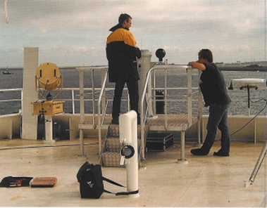
The magnetic standard compass and the compensation engineer at work
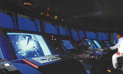
A view on the bridge
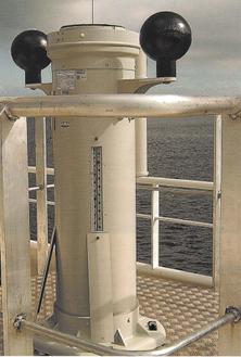
1.1.2. Gyrocompass
Ships of 500 GT and upwards have to be fitted with a gyrocompass. There are 3 different types of gyrocompasses:
- Dry
- Fibre optic.
The gyrocompass depends contrary to the magnetic compass, on the earth's angular velocity, as it points itself to the earth's axis of rotation.
The gyrocompass consists essentially of a gyroscope, which, when spinning at a sufficiently high speed will have its axis maintaining a constant direction in space, regardless of how the supporting rings are tilted or turned. This property is known as the rigidity in space. Magnetic forces do not have influence on the maintained direction.
The gyrocompass is installed in a binnacle, where the spinner is installed inside a ball shaped housing. This ball floats in a special liquid, with a specific gravity keeping the ball vertically accurately inside its surrounding housing to allow the spinner to seek its direction in space. Inside the floating ball, an electric motor is installed, with the rotor as the gyro-spinner. Electric contacts are ensured by sophisticated sliding devices.
When suitable controls are applied, the axis of the gyroscope seeks the direction of the true north. Because of the rotation of the earth, the axis of the gyro appears to move, although maintaining its direction in space. This motion is a combination of drift and tilt, together the apparent motion. Drift is the horizontal deviation from the selected direction in space, due to the earth's rotation. The magnitude and direction of drift is depending on the latitude. By creating friction, which is already there from the liquid the ball floats in, the axis points itself in the direction of the earth's axis, i.e. in the direction of the true north. Tilting is a result of the latitude. When at the equator, the direction of the axis is the same as to the horizon. When at higher latitude, the direction to a point above the north pole of the earth results in a vertical angle with the horizontal.
This can be adjusted by gravity, i.e. by a weight or a system with adjustable floats in mercury. Added weights give the ball a position parallel to the horizon. Settings depend on the actual latitude. The ship's speed is producing another deviation. The gyro will adjust itself rectangularly to the resultant of the true course of the vessel and the eastgoing direction of the earth. The instrument itself also has some constant deviation.
Above deviations are corrected by various electronic devices. The binnacle is normally installed in a technical room near the wheelhouse of the ship. Often at a lower deck, to reduce transversal forces due to the ship's movement. At various places repeaters are installed, showing the directional information wanted for navigation (or other purposes). Normally at the steering position, at both bridge wings, sometimes near the magnetic compass for easy calibration of that compass.
The principle of the dry gyro is the same as of the liquid gyro. However, the big advantage is there is no maintenance required during its MTBF (mean time between failure).1.1.3. Fiberoptic Gyrocompass
The last development of the gyro principle, also electrical, is the Fiberoptic Gyrocompass. This is a complete solid unit, which has no rotating or other moving parts. It is based on a laser beam sent into a horizontal glassfibre coil, split in two halves when entering the coil. One half goes left, the other half right. When the coil has not turned, both beams return at the entering point at the same moment. If the coil has turned, the beams do not return at the starting point at the same time, resulting in a phase difference. Three coils at the x, у and z axis, enable the calculation of the true north. The device is made in solid state and needs only an short settling time.
1.1.4. Fluxgate compass
A fully electrical compass is the Fluxgate compass. Two coils under 90° produce an electric current by the magnetic flux passing through the coils. From the difference in measured current the direction of the magnetic north can be calculated.
1.2. Off-Course Alarm
When a ship, whilst on passage changes course unwanted, an alarm has to sound. Often this is a device coupled to the gyro. Also the magnetic compass must be used for this purpose.
Allowed degrees off course are to be set. When coupled to the gyro this can be done automatically.
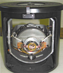
A gyrocompass opened up. The grey cylinder in the center contains the gyro spinner. Cooling is provided by liquid
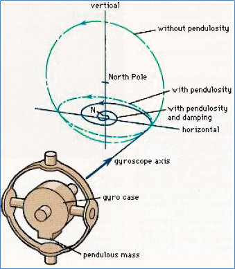
Circular line shows the apparent motion of the axis of a gyroscope around the pole star in the absence of a pendulous mass.
The addition of the pendulous mass (lower drawing) converts the circular motion into an ellipse; the ellipse can then be damped out
and the gyroscope becomes a gyrocompass pointing to true north
1.3. Radar
A RADAR (Radio Detection and Ranging) with automatic plotting (ARPA) function and rotating trans- mitting/receiving aerial, usually the X-band (frequency 8-12 GHz). For ships bigger than 3000 GT a second radar has to be provided, usually an S-band radar in the frequency range of 3-4 GHz. The reason to select two radars with different frequency bands is their different capabilities to cope with the environmental conditions such as fog, rain, sea clutter.
A radar installation comprises a transmitter/receiver, and a rotating antenna. A display shows the outcome. The transmitter/receiver is a box mounted directly under the antenna. The antenna or scanner, is installed in the radar mast, usually on top of the wheelhouse.
The scanner is rotating. A very short pulse is sent from the raytube to the scanner mirrors and leaves the scanner as a narrow beam. When this beam bounces on an object, part of it can be received in the scanner. From the timespan between sending and receiving, the distance to the object can be calculated.
The direction is given by the position of the scanner, relative to the ship's centerline. The bounced pulse is seen as a dot on the display.
The reach of the radar is determined by the height of the scanner and the height of the target.
Sensible precautions
If radar equipment is to be worked with under power in port, sensible precautions would include ensuring that:
- the scanner is rotating or if the work requires the scanner to be stationary, that it is directed to unoccupied areas, e.g. out to sea,
- no one looks directly into the emission side of a slotted wave guide (open box type) scanner,
- no one is able to position themselves between the output horn of the transmitter and the reflector of larger scanners,
- the risk of being hit by a rotating scanner is not overlooked if work close to the installation is necessary.
1.4. Global Positioning System, GPS
GPS is simple to use and so reliable that nearly all ships, from small yachts to the largest ships at sea, are fitted with one or more GPS receivers.
GPS is an independent auto-position fixing system, with omnidirectional aerial. The input data are produced by satellites. The system was originally designed for the US defence department but has been made available for civilian use. Europe is working on an alternative independent system, Galileo.
DGPS or Differential Global Positioning System, is a more accurate GPS, by the installation of an additional signal from a reference transmitter. The location of this transmitter is accurately known, so improving the outcome of the position calculation.
Due to the limited reach of this additional transmitter, this is a local improvement.
Global positioning systems operate on low power signals, transmitted by a large number of satellites, which orbit the earth at an altitude of 20,000 kilometres. Normally there is input from some 8 satellites at every moment.
This (D)GPS gives not only the actual position in coordinates, but when the receiver (the ship) is moving, it calculates also speed and course over the ground.
1.5. Autopilot
1.5.1. Automatic course function
Automatic pilots are control devices that compare the actual course on the gyrocompass with the set course, and take corrective measures if the actual course is deviating from the set course. Most of these control devices are now adaptive, which means that it adapts to the ship's characteristics by applying minimum rudder angle to get back to the set course. Autopilots can be adjusted for gain, maximum rudder angle and maximum rate of turn.
The modern autopilots are so sensitive that they operate the rudder at a minimum deviation of the set course before the helmsman would notice. This way steering a more straight course than a helmsman would do. A straighter course saves fuel and time.
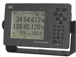
Display GPS
1.5.2. Autotrack function
GPS positioning giving course and speed via ECDIS or GPS over the bottom makes it possible to steer according to a planned track. Way points can be added and at the way points the vessel will slowly turn to the next track, after a warning and being acknowledged.
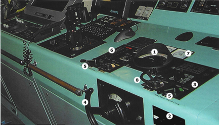
3. Autopilot
4. Follow-up steering wheel
5. Non-follow-up steering wheel
6. Steering-gear controls and alarms
7. Rudder angle indicators (twin rudders)
8. Course selector
1.6. Speed and Distance (Log)
On ships over 500 GT the speed and distance through the water has to be measured. One log with speed and distance indication through the water has to be installed. This can be for instance an electromagnetic log. In shallow water the so-called Doppler log can measure speed through the water and over the ground, water track or ground track. This can be chosen at the display.
Dual-axis logs measure speed in forward and aft direction as well as transverse movements. The latter for very large ships (tankers, bulkcarriers), to control the impact forces on the jetty during mooring.
1.7. Rudder angle indicator
The physical position of the rudder has to be shown on a display. Normally this is displayed on a deckhead-mounted indicator visible from everywhere in the wheelhouse.
1.8. Rate of turn indicator
Rate of Turn Indicator has to be installed on ships of 50,000 GT and upwards. The rate of turn is important for large ships, to determine the time needed to come to a decided course.
In advance of a turn, the helm has to be moved in the position to get the ship turning. Especially large ships need time to start to react.
In the bridge console there are displays for RPM and turning direction of the propeller. Or the pitch in case of a controllable-pitch propeller.
Displays are also installed on the bridgewings, as these parameters are very important during manoeuvring and mooring.
1.9. Wind and sound
Ships with an enclosed wheelhouse, which are vulnerable to wind during manoeuvring, are to be fitted with a wind indicator and a sound reception system. The latter consists of microphones outside and a speaker system inside enabling to establish the incoming direction of the outside sound.
1.10. Echosounder
The water depth under the ship is measured with an echosounder. A transducer in the ship's bottom sends a sound pulse downward, and receives the bounced pulse. The distance between ship's bottom and seabed can be calculated from the time between sending and receiving.
The speed of the pulse through the water is more or less constant. Adjustment settings can be made for the ship's draft. An alarm can be set at any depth below the transducer. The sent sound beam has a conical shape, with the top of the cone at the transducer.
1.11. Daylight Signal Lamp
All ships over 150 GT, must have a daylight signal lamp. The source of electric power has to be independent of the main power supplied to the wheelhouse equipment. Often an ordinary battery is used,
1.12. Navigation Lights panel
In the wheelhouse an alarm and indication panel is to be installed to control and monitor the navigation lights. Most of the time next to this panel is a control panel for the signal lights like NUC (Not Under Command) lights.
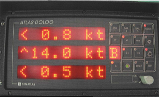
Doppler log display showing speed in bottom track mode and sideways speed bow and stern
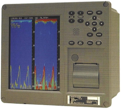
Echosounder display showing depth under the kee
1.13. Voyage Data Recorder
Passenger ships and ships other than passenger ships of 3000 gross tonnage and upwards constructed on or after 1 July 2002 must carry voyage data recorders (VDR, Black Box) to assist in accident investigations. Details can be found in SOLAS.
Such a unit consists of a data acquisition unit, acquiring all necessary data from the various instruments and a data capsule. The device records information regarding course, speed, communication, alarms, alterations, engine particulars and what has been said in the wheelhouse. Data can, if wanted, be transmitted to the shorebase of the vessel.
Like the black boxes carried on aircraft, VDRs enable accident investigators to review procedures and instructions in the moments before an incident and help to identify the cause of any accident.
The data acquisition cabinet is normally installed in or near the wheelhouse, the data capsule on the wheelhouse top. The latter has to be installed so, that it floats up in case the ship sinks. The device has to be tested yearly by an approved company.
1.14. Electronic Chart Display (Ecdis)
Instead of paper charts, the information is displayed on a computer screen. On this screen also the ship's position is shown.
The charts can be raster-type, which means that they are scanned paper charts, or vector-type, fully digital. The last type has advantages. The electronic chart can be combined with AIS and Radar, this means that all information can be made visible on one screen. Updates of the charts are carried out digitally. A second system has to be provided for back-up. Paper charts also can be the back-up, but this means that they have to be corrected.
Raster-type charts are not approved for paperless sailing.
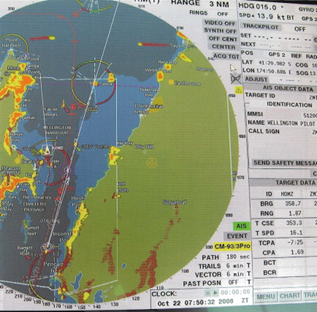
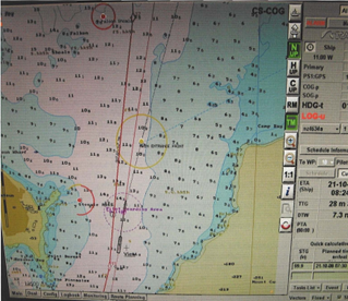
Above the AIS displayed on the radar screen. Below the ECDIS display of the same area. The ship is displayed on both screens
Иностранный язык: en