 +7 (812) 4-673-673
Network Installation SAILOR AIS, GNSS/DGNSS, Navtex, and Control Panel
28.04.2016


Иностранный язык: en
Network Installation SAILOR AIS, GNSS/DGNSS, Navtex, and Control Panel
Internal number 95-141788-A document.
Scope and identification.
The purpose of this document is to establish a baseline for addressing SAILOR network settings of the internal and external communication configuration. The document explains our recommendations on the use of an Ethernet network between the above devices SAILOR. In addition, instruction will be developed to connect the Ethernet interface to other types of SAILOR, as well as the third-order devices.
This version of the manual covers only the redundant Ethernet network connected to the internal network devices SAILOR, who were listed in the document title. Description of the relationship with the third order of devices from other manufacturers, such as ECDIS is contained in a separate manual.
SAILOR 6282 AIS transponder, receiver SAILOR 6390 NAVTEX receiver SAILOR 6588 GNSS / GNSS Control Panel SAILOR 6004 - provide a device for the Ethernet redundant topologies that would increase the reliability of the network.
In order to carry out the installation in accordance with SOLAS requirements, product certificates to be taken into account at all times.
For all other installation issues, please refer to the installation instructions for each device.
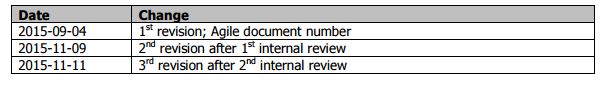
Revision of data
define
CP - SAILOR 6004 Control Panel
RSTP - Protocol Rapid Spanning Tree
TMA - Application Management Link Thrane, running on a PC with Microsoft Windows, can be downloaded at www.cobham/satcom under Service & Support.
Priority applications - When the application for a control panel SAILOR 6004, you can choose whether the app can be set as a priority. Each SAILOR 6004 2 Applications may be selected as priority applications. These applications will be available both via the HOME button, and use the shortcut at the bottom of the screen buttons.
Technology RSTP
Blocks of the SAILOR, described in this document, use RSTP technology in their network interfaces. The advantage of the technology is the RSTP redundancy under certain conditions. This allows in case of connection failure network reconfiguration automatically activate within 1-6 seconds, which typically allow the connected devices continue a connection without interrupting service.
RSTP requires the device to a minimum, there has been two Ethernet ports for connecting to other devices.
Configuring RSTP should be available on all devices in the network.
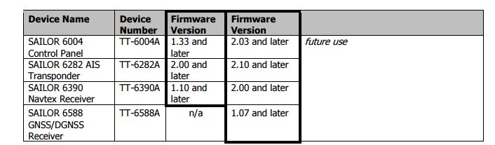
RSTP SAILOR products
The following default SAILOR devices available for RSTP and therefore can detect and use redundant Ethernet network:
If the device is not in the list, it can not be used in any of the topologies.
Note: Make sure that all the devices have at least the necessary firmware version. Use of devices with older firmware may jeopardize redundancy degrade performance machine interface, and even degrade the functionality of the devices SAILOR.
Note: Connecting the devices are not listed in any of the PSTP topologies could jeopardize redundancy, reduce the performance of applications running interface, and even impair the functionality of the devices SAILOR.
Note: Keep in mind that the Ethernet cables only provides redundancy if they are physically separated with each other to install.
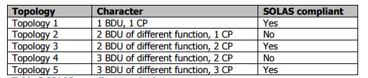
Recommended topologies that use RSTP
This chapter lists several topologies for network devices that are listed in the table above.
Not all of these topologies correspond to SOLAS, see table below:
Note: There is currently no management interface protocol for SAILOR BDUs via Ethernet from non SAILOR control units. Each SAILOR BDU supports multiple NMEA / UART commands for working with such equipment as a third order of ECDIS, please refer to the manual for specific instructions BDU's.
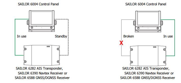
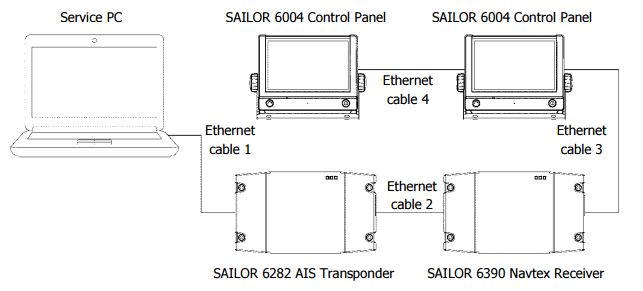
Topology 1:2 devices
In this topology, the system will continue to operate even if one of the two cables to be accidentally removed or broken down due to mechanical or electrical stress. When installing 2 cables are permanently connected between the 2 devices. The order of the ports does not matter.
The following three pictures show the same installation in different environments:
Figure 1 shows an installation.
Figure 2
a) shows the normal operation where both cables can be used RSTP protocol via Ethernet cable 1.
b) indicates that the Ethernet cable 1 failure is detected, and RSTP protocol uses Ethernet-cable 2. The transition between the two states is automatic.
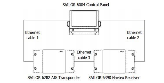
Topology 2: AIS, NAVTEX and 1 Control Panel
In order to have a sound system, 3 cables are used in a ring topology. Connection does not matter. The system will always send packets to the most effective way.
Note: This topology is not recommended, as it may fail in 6004. SAILOR Control Panel will lead to loss of control over the SAILOR 6282 AIS transponder and SAILOR 6390 NAVTEX receiver. Topology 3 can solve this vulnerability.
Topology 3: AIS, NAVTEX and 2 control panel:
To have a reliable system uses 4 cables in a ring topology. Connection is important for cases where there is more than 1 pereryvaniya connection.
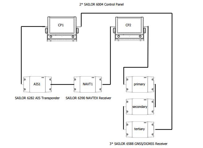
Topology 4: AIS, NAVTEX, DGNSS 3 and 2 Control Panel
In order to have a sound system, 7 cables are used in a ring topology. Connection is important for cases where there is more than one interruption.
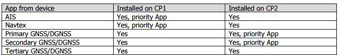
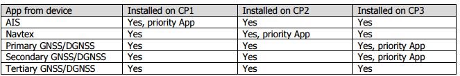
Install applications on the SAILOR 6004 control panels is recommended as follows:
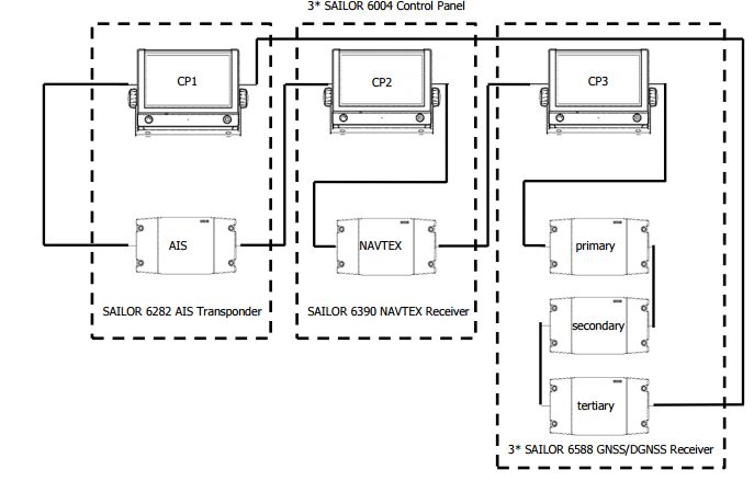
Topology 5: AIS, NAVTEX, DGNSS 3 and 3 Control Panel
In order to have a reliable system of cables 7 are connected in a ring topology. Connection is important for cases where there is more than 1 pereryvaniya connection.
Install applications on the SAILOR 6004 control panels is recommended as follows:
Testing and Maintenance
Connecting service PC
To connect your PC to the service system, you need to disconnect one cable from one device and connect it to the computer, as shown below.
Initial System Configuration
1. Check the firmware version for each device: Use your computer service and TMA application. In the case of existing requests for firmware upgrades: upgrade the firmware to create a ring topology.
2. Install the necessary device to the selected layout and connect all cables.
3. Set the MMI applications for AIS, GNSS / GNSS and / or Navtex in the control panel, as described in the user manuals.
Testing the backup system
4. Open MMI Applications for Navtex and / or AIS, to check for errors or improper configuration.
5. When you go in an unmistakable state, disconnect one end of any of the Ethernet cable in the ring and make sure that does not appear the words 'lost connection' to any of the control panels for the AIS, GNSS / DGNSS or Navtex.
6. Reconnect the cable and repeat the test on the type of error 'Connection lost'.
7. Repeat steps 5) and 6) for each of the ring Ethernet cables.
8. The 'lost connection' throughout the procedure, to identify errors.
9. When the two Ethernet-disconnect cables in the ring, at least one control panel must indicate an error.
Troubleshooting
If the test shows the system error 'lost connection' when one of the connecting cables Ethernet disabled one or more other cables Ethernet link are subjected to crash.
If only one Ethernet cable is subjected to a crash, the system will continue to function without alarm as RSTP avoids the use of a defective cable. In this state, the error 'Connection lost' will occur if further remove another cable. Therefore, a defective cable is the one that you can remove from the system without causing an error 'lost connection'.
If several Ethernet cable binders subjected to crash, you must repeat steps 5-8 for all cables is no longer reflected 'the connection is lost.'
Иностранный язык: en