 +7 (812) 4-673-673
RADIOLOCATION part 2
24.12.2013


Иностранный язык: en
RADIOLOCATION part 2
X-band and S-band
When the weather is clear there is no significant difference between the X-and S-bands. However, in heavy rain radar operating in the S-band gives a slightly better detection than radar operating in X-band.
Radar resolution
There are two important parameters that affect the overall resolution radar capability: the resolution in azimuth and range resolution.
Azimuth discrimination
Azimuth discrimination - is the ability to show the radar screen as separate tags echoes from two nearby targets located at the same distance from the radar. It is proportional to the antenna length and inversely proportional to the wavelength. Length radiate- ator antenna must be capable of resolving azimuth better than 2.5 ? (resolution requirements IMO). For X-band usually this condition is satisfied for the length of the radiator at least 1.2 meters (4 feet). For radars operating in the S-range, the required length of the radiator is not less than 3.6 m (12 feet).
Range resolution
Range resolution - the ability of radar display on the screen as separate tags echoes from two nearby targets located at the same relative bearing of radar. It is defined only by the pulse duration. For example, if the pulse duration of 0.08 ms resolution higher than 40 m .
The test purpose, which are used to determine the resolution capacity in azimuth and range, are radar reflectors with reflection area of 10 m2.
Accuracy bearing
One of the most important characteristics of the radar is a precision bearing determination on the target. Accuracy bearing mainly depends on the width of a radar beam. However, bearing usually measured relative to the direction of motion of the vessel, so that an important factor in ensuring the accuracy of the azimuth alignment accuracy is heading line during installation. To minimize the error in determining the bearing to the target, set the echo from the target to the extreme position on the screen by selecting the appropriate distance range.
Range measurement
Measuring the distance to the target is also an important function of the radar. In general, there are two means of distance from the fixed range rings and the movable ring marker (VRM). Fixed range rings are displayed on the screen at a specified interval and provide a rough estimate of the distance to the target. Diameter PKD need to change so that it touched the inside edge of the goal, allowing the operator to get a more accurate measurement of the distance.
Minimum distance range
Minimum distance range determined by the shortest distance, which (using the scale range of 1.5 or 0.75 nautical miles) with the aim of reflecting area of 10 m2 is not discharged to the point the location of the antenna.
Minimum distance range depends on the length of the pulse height of the antenna and signal processing method (eg, suppression of the main pulse and digital quantization). Use smaller range scale, as they give better resolution and clarity. Resolution MSC.192 (79) of the International Maritime Organization requires a minimum distance range was not more than 40 m radar this series satisfy this requirement.
Maximum distance range
Maximum detection range, Rmax, varies greatly depending on the height of the antenna above the target height of the sea, the size, shape and material goals, as well as atmospheric conditions. Under normal atmospheric conditions, the maximum range distance equal to or slightly less than the radar horizon. Radar horizon on Optical approximately 6% due to the diffraction phenomenon of the radar signal. Rmax can be found from the following formula.
Rmax = 2.2 x (? h1 + ? h2)
where, Rmax: radar horizon (nautical miles):
h1: antenna height (m)
h2: target height (m)
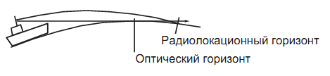
For example, if the height of the antenna above the sea level of 9 m, and the target height of 16 m, then the maximum range is the range:
Rmax = 2.2 x (? 9 + ? 16) = 2.2 x (4 + 3) = 15.4 nm
The detection range is reduced because of the influence of precipitation (which absorbs radar signal).
False echoes
Sometimes echoes appear on the screen in places where there are no goals, or, conversely, disappear, even if there is a purpose. These cases can be recognized, if you understand their causes. Typical false echoes are shown below.
Multiply reflected echoes
Multiply reflected echoes occur when the transmitted pulse is reflected from an extended object, such as a large ship, bridge, or breakwater.Echoes reflected two, three or more times can be observed on the screen at a distance greater than the actual distance to the target in two, three or more times, see the figure below. Multiple reflection echoes can be reduced or completely removed, reducing the gain setting (sensitivity) or properly adjusting function suppression from the sea.

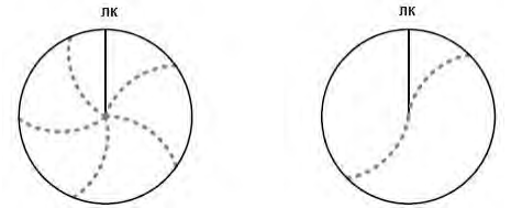
Echoes sidelobe
Each time the transfer pulse of the radiation outgoing from the side of the main beam is called 'sidelobe' diagram of the antenna. If the target is positioned so that from it reflected pulses as the main beam and sidelobe antenna, we obtain more echo signals from the target are located on the sides of a true echo in the same range. side echoes usually appear at short ranges range and from stable targets. They can be lessened by a smooth gain reduction or adjust the noise reduction function from the sea.
Virtual image
A relatively large target close your vessel can be displayed on the screen in two positions. One image is a true echo reflected directly from the target, and the second is a false echo, which arose as a result of the effect of specular reflection from a large object on his vessel or near (see Fig. below). If the vessel is too close, for example, a metal bridge-like false echo may temporarily be visible on the screen.
The informal sector
Chimneys, flues, masts and derricks in the path of the radiation of the antenna unit, prevent radar radiation. If the antenna is greater than the angle of shading a few degrees, it may form a 'blind' sector. Within this sector, the goal can not be detected.
Interference from adjacent radar
If another radar operating in the same frequency range, is close to his ship, the screen may show some noise. This interference is composed of a series of dots
Various kinds of host. In many cases, these terms do not appear in the same regions of the screen, and can easily be recognized.
If closely spaced radars same model, the pulse repetition frequency which is practically the same. Therefore, noise may appear in the form of concentric circles. Suppression effect can be enhanced by selecting different pulse repetition frequencies of closely spaced radar.
Иностранный язык: en