 +7 (812) 4-673-673
INFO: RADIOLOCATION part 1
18.02.2014

Иностранный язык: en
INFO: RADIOLOCATION part 1
The operator must have a good understanding of the features of display information about the environment on the radar screen to use all of its features when operating the boat. When observing the surroundings on the radar screen, the operator must submit all well its advantages and limitations. For a better perception of the information on the radar screen, it is important to gain experience observing their surroundings in good weather, when there is a possibility of comparing the target with its echo on the monitor. Radar is used to monitor the movement of the elements of his ship and
surrounding targets detection buoys and other aids to navigation when entering the port positioning vessel when sailing in coastal waters by measuring distances and bearings noticeable onshore facilities and to monitor the situation and movement of heavy rains, with the appearance of the corresponding marks on the screen .
PROPAGATION
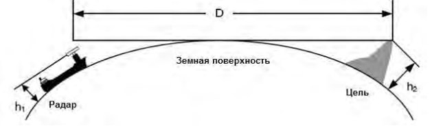
Radar beam propagates almost in a straight line over the curved surface of the Earth. Propagation conditions vary depending on the condition of the air through which the beam passes. Under normal conditions of propagation distance (D) propagation radar approximately 10% higher than the range of optical visibility horizon. Distance (D) is calculated as follows:
D = 2.23 (? h1 + ? h2) (miles)
h1: Height (m) the installation of the radar antenna above sea level.
h2: Height (m) above sea level objectives.
The figure shows a diagram of the radar beam propagation distance under normal propagation conditions, taking into account the earth krivizmy
surface.
For example, when the antenna height of 10 m, (a)
- Height of target detection on its 64 mile range scale should be at least 660 m
- When target altitude 10 m, distance radar detection should be approximately 15 miles.
In addition, the maximum distance target detection depends on its size and ambient weather conditions, so the detection range can be increased or decreased under the influence of these factors.
Reflected from the target
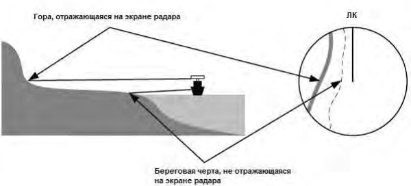
The intensity of the signal reflected from the target, depends not only on its size and height, but also the material and shape. The intensity of the reflected signal
targets having greater height or dimensions not necessarily be higher. In particular, the reflection of the shoreline depends largely on the terrain. If the shore is very flat, the reflection of the mountains, located in the hinterland, may appear on the radar screen, as shown below. Therefore, the distance to the shoreline should be measured very carefully.
INTERFERENCE FROM SEA WAVES AND RAIN
In addition to the useful signals reflected from surrounding vessels and onshore facilities in the fall of the radar receiver noise associated with the reflection from the excitement of the water surface, as well as precipitation. Reflections from the water surface are called 'interference from rough seas,' and reflections from rain or snow is called 'interference from atmospheric precipitation.' This interference is suppressed by means of special devices.
Interference from rough seas
Interference from rough seas appear as illumination with the center of the screen sweep, the intensity of which decreases towards the edges of the screen depending on the size and shape of the waves. As a rule, an increase in the intensity of the interference wave height increases and also displayed on the screen for long distances. When sailing in stormy conditions when the level of interference from the high sea state, it is hard to recognize the echo weak targets against interference.
Interference from precipitation
Interference from precipitation are video signal appearing on the radar screen at a position corresponding zone of precipitation. Interference varies depending on the intensity of precipitation. With increasing rainfall interference becomes more intense on the screen
radar, and when heavy rain image noise practically coincides with the map coast. Moreover, due to radio wave energy absorption drops
rain or snowflakes, the ability to detect targets against interference from precipitation, or a target located behind the zone of precipitation decreases.
DISPLAY SIGNALS SART
SART ((Radar defendant) is rescue equipment required GMDSS (Global Maritime Distress and Rescue), which is used to detect distress at sea. SART emits a signal in the frequency range of 9 GHz. Upon irradiation device radar beam operating in the 9 GHz band and placed on the ship or rescue aircraft, SART emits a series of signals to indicate the disaster site.
For better signal detection SART is necessary to make the following settings:
- Scale: 6 or 12 miles
- Regulator [SEA] (Wave) to minimum (fully counter-clockwise)
- Automatic noise reduction from rough seas: Disabled
- Setup Mode: Off (for noise reduction)
- Suppression of interference from neighboring radars: Disabled
-
Digital Signal Processing: Disabled
WARNING:
When you configure the points 1 - 6 for detecting SART signals, close to its target vessel may be masked by noise. It is therefore necessary to take additional measures to monitor the environmental conditions in the near field for collision avoidance and prevention of groundings.
In the presence on board of two or more radar, set one of them operating in the 9 GHz band to receive signals RLS, while others use in order to ensure the safety of navigation. After detecting SART adjust the radar to be used for navigation safety.
Иностранный язык: en